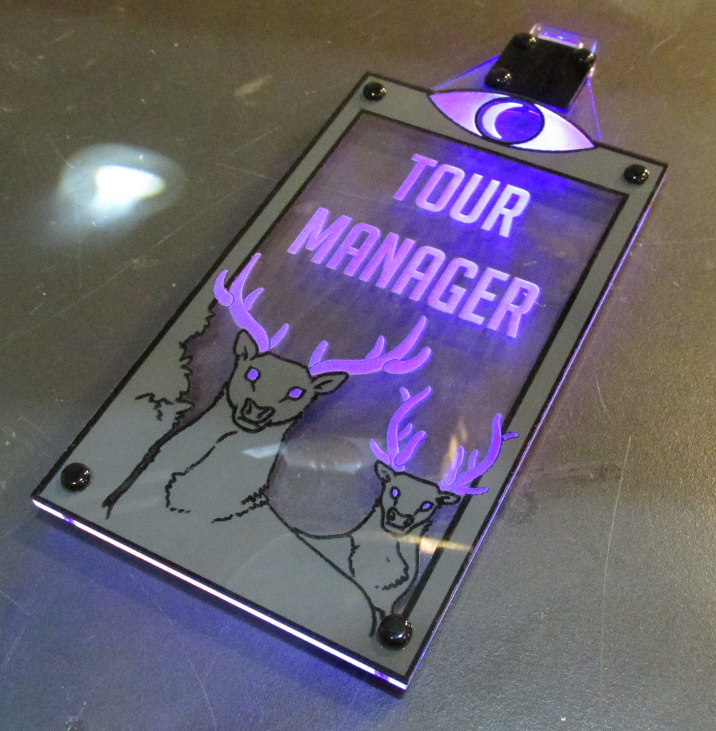
Archive for the ‘Quick Projects’ Category

WTNV Glow Badge!

Wednesday, May 28th, 2014

close-glowing

I had the honor of helping my friend Hannah make a badge for Lauren, the  Welcome to Night Vale tour manager.  She made the kick ass art for the badge and it was up to me to actually make it work. I've made a number of glow badges before but for this one I had to incorporate some multi-colored artwork, make it glow purple and have an on/off switch. All of which I had not tackled yet, but I like a challenge from time to time.

The switch was straight forward, but making it purple is a little more difficult. Purple LEDs are available, but they're actually UV, and they're not super bright.  Using a red and a blue LED on the same power source isn"t possible like I've done with previous glow badges without current limiting resistors since the red LED has a much lower forward voltage. I overcame this limitation by adding a couple optional current limiting resistors to two independent LEDs on a custom PCB:

board-back

board-front

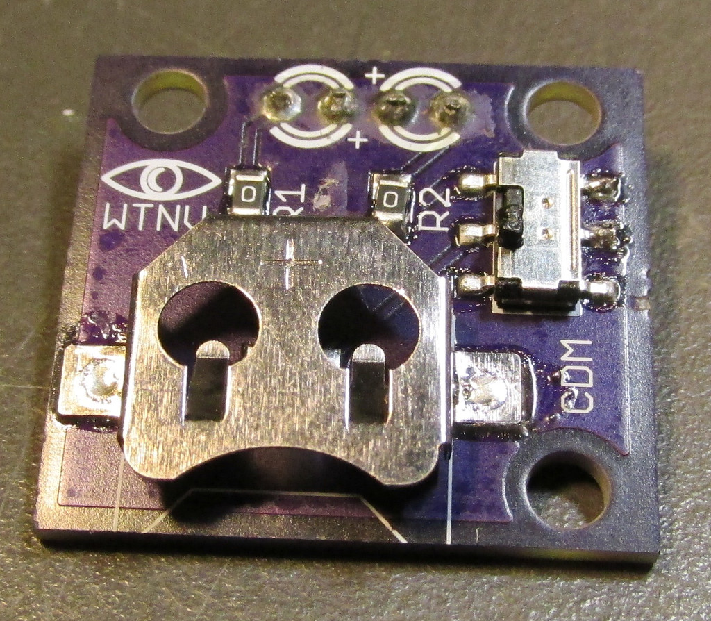
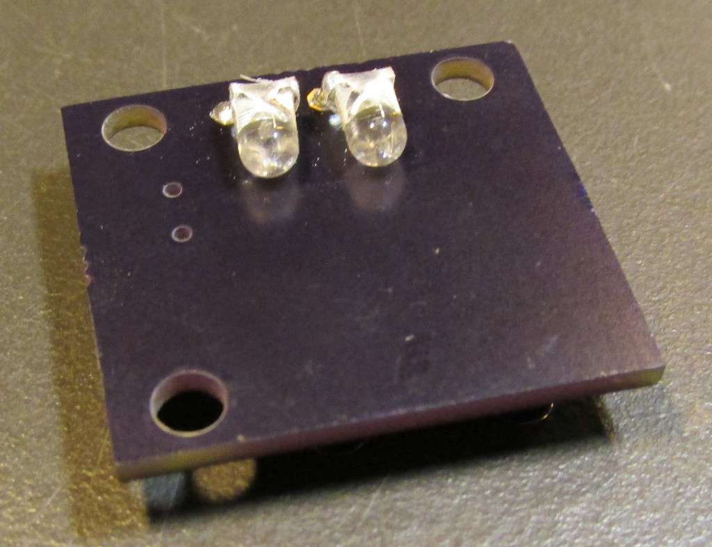
In the pics I have two zero ohm resistors in place. This is because this particular board was a test board that has two white LEDs on it. I tried two different strategies for getting a bright purple, two white LEDs with a filter, ane one red LED and one blue LED with different current limiting resistors to mix them appropriately. The red/blue combo turned out to be the winner (430 ohm resistor on the red LED, zero ohm on the blue). It was brighter than the two white LEDs with filter and more vibrant overall.

For the graphics, I etched the outlines of each color on to a sheet of 1/16" acrylic and used spray paint and selective masking to get the color fills I wanted. Here's a pic of the color plane after applying black and removing the masking for the gray areas  before painting them in:

paint-black

If I had more time I would have gotten the graphic layer printed rather than painted it on myself (I've used some local printers to do some awesome stuff with acrylic on UV cured inkjet printers). After the graphic layer, PCB, and laser etched glow layer where completed, I attached everything with expanding push rivets. Here's a pick of the white LED and filter setup:

badge-parts

badge-assembled

And here's another pic of the final red/blue badge in all it's glowy glory:

badge-lit


Share

The Year of the Skull

Friday, November 1st, 2013

Bobcat Skull

In this special Halloween update I'm sharing some of the stuff I made for the occasion. I had a bit of a skull theme going this year. It started when picked up a number of cheap skulls from some trappers at the KC renfaire and I using them for a couple projects for Halloween. First off the Halloween wreath:

Skull Wreath

skull wreath

It's basically just a grapevine wreath, a few artificial flowers, and a few small skulls held together with wire and hot glue. The jaws of many of the skulls were free moving so I hot glued most of the jaws in place at their base to keep them together. It might need some additional garnish (I'm thinking snakes... yeah snakes), but it looks fairly creepy so far. I really like the deer skull centerpiece.

Next we have my attempt at a new tradition in addition to the Halloween wreath, the Halloween tree:

Halloween Tree

It's basically just a fallen limb with holes drilled in it and pose-able black stems from Hobby Lobby stuck in and the bases of those stems reinforced with floral wire with a little moss thrown in. It's all stuffed in a small metal barrel we had around the space. Of course after it was assembled and posed I threw some more skulls on it for decorations:

Skulls

Mink Skull

Turtle Skull

I like the asymmetry of the whole thing. The twisted and gnarled limbs really give it some character. Hopefully I can find a place to stow the thing over the next year so I can make some nice creepy ornaments for it when I pull it out again.

Lastly, since there was already casting stuff being used in the Hammerspace monster maker classes and I needed a welding mask, I threw this together:

Failed Cast

On the right is a failed cast, from which I learned that Alumilite, at least in reasonable volume, is not good of slush casting as it sets up almost instantaneously. The base design was done by my friend Hannah:

Mask

From there I blended the design a bit with a coyote skull. Here's a pick of the sculpt in progress:

skull mask wreath

It's meant to incorporate a pair of welding goggles and have space for a respirator so I can wear it while watching the plasma cutter work. Here's the latex mold with plaster jacket after the clay's been removed and a couple pours have been done (thanks to Dave at Hammerspace for helping me make the mold and do the pour):

mold

I originally had the goggles in the sculpt but I messed the threads up on the first pour so I cut them out on the second pour and glued an extra set I had in place:

mask-inside

Here's a pick of the test fit (cast in Smooth-Cast 320) before painting:

Dog Skull Mask

Here's some pics with the respirator in place after Brandon Mohn airbrushed it up:

welding mask

mask-side

I threw this on together in a couple days so there's a few things that need to be fixed so I'll probably get another pull off the current mold and keep it around for when I actually want to fix it up. The goggle components actually threaded into place with the first pour so I'm optimistic about incorporating goggles into future sculpts. For now I'll probably just add a second elastic band a bit higher up from the goggles to help keep it from sliding down my face when not using a respirator, but other than that it's pretty usable in it's current condition.

Share

The Carbon Filter Experiment

Monday, March 19th, 2012

I'm going to be moving all my stuff to the new CCCKC HQ, Hammerspace by the end of March, and I've taken this opportunity to experiment with building a carbon filter for the laser cutter exhaust to cut down on VOCs and nasty smells generated by the machine.  Being a cheapskate frugal, I decided to try to make a very cheap setup that's easy to build, seal up, and fill (and refill).  Here's some more pics of my first prototype:


The setup consisted of a 5 gallon bucket with rubber seal to form the main enclosure, a 3 gallon bucket to hold the carbon, a plastic coffee can, some thin aluminum screen, 4" OD toilet anchors to act as ports, and a tube of silicone caulk to seal everything up.  All components, except for the active carbon itself and the coffee can, can be found at a Home Depot for about $20.

Basically, I took the plastic coffee can, cut the sides out, and added some screen held in place with silicone to be my innermost support.  For the 4" port on the bottom, I used a toilet anchor and cut 4" holes through the bottom of a 5 gallon bucket and a 3 gallon bucket and sealed everything up with silicone.  A small ring of PVC that press fit the 4" OD toilet anchor was added for mechanical support (you can kinda see it in the pic where the 4" ducting is installed below).

The 3 gallon bucket was used to form a support cage which screen was attached to, much like the coffee can, but this time the holes were cut with the same 4" hole cutter that was used to make the holes for the 4" inlet (toilet anchor).  The active carbon is poured in to the 3 gallon bucket and forms an envelope around the coffee can. Once filled, the 3 gallon bucket lid is installed.  I probably took a little too much material out of the sides of the 3 gallon bucket, as it was a little difficult to get the lid on it because the sides kept collapsing a bit.

It took a little less that 3 quarts of active carbon to fill the void in the 3 gallon bucket (about 60 oz. by weight).  I was surprised that very little of the active carbon actually made it through the screen (a little less than a tablespoon) while filling.  After filling, I attached a 4" hose to the inlet and sucked some air through the filter (I would suggest you do this along with filling the filter outside) with a small dust collector motor. Airflow didn't seem particularly impeded by the filter so it should work well with the dust collection system in the shop.

In normal operation, air from the laser cutter would come in the coffee can where it would pass through 1.5"-2" or more of active carbon between the 3 gallon bucket interior and the coffee can exterior, then out the lid of the 5 gallon bucket.  I'm eager to actually put this thing to the test here in the next 2-ish weeks and see if it actually works for filtering out the nasty gasses put off by the laser in operation.

Share

Building a BeagleBone Enclosure

Saturday, January 7th, 2012

I got to play around with a borrowed BeagleBone board to get some kernel stuff working for a friend. While playing around with it I decided to throw together an enclosure kit and a sled for the thing as well.  The sled is pretty easy to figure out, but the enclosure takes a little more effort to put together, so I thought I'd do a quick write up outlining how to assemble it.

First off, peel the masking off all your laser cut parts.

laser cut front panel

peeling protective film off of laser cut part

Next, you'll mount the BeagleBone to the bottom using 14mm M3 bolts, M3 nuts, and 1/4" OD 1/4" high nylon standoffs.  Make sure to mind the resistors on the back side of the board around the power connect (labeled R150 and R189).

zoomed image of R150 on BeagleBone

BeagleBone mounted

Next, you need to partially thread all the remaining M3x14 bolts into the T-slots of the spanning pieces and the end caps.  This is physically possible without assistance, but it's hard.  You'll want to save yourself some time by using some scotch tape and securing the nuts in place before inserting the bolts.

Nuts held in place with tape

Once this is done, you can slide in the bottom, sides, and top before finally tightening down the bolts.  Don't overtighten the blots, the enclosure is all acrylic and it will crack under extreme stress.

Bottom Installed

Sides Installed

Top Installed and Bolts Tightened

Other Side After Assembly

You can simply leave the top off if you want easy access to the expansion headers.  The Adafruit BeagleBone proto cape will even fit with the top off:

Here are some additional pictures of the enclosure with the USB host and peripheral interfaces plugged in (notice that you can see the status LEDs above the peripheral connection):

BeagleBone USB host connection through enclosure

Grab an enclosure kit including handy hex wrench from my store and you can grab all the design files and BOM from the Thingiverse entry.

BeagleBone SledYou can grab a sled kit there as well, if you feel like your BeagleBone would like a little more of an open air prototyping environment. You can find the design files for the sled, BOM, and instructions on its Thingiverse entry here.

Share

Testing and using an ATX power supply outside of a PC

Tuesday, December 20th, 2011

ATX Power Supply Dongle

Here's a pic of a quick little dongle I threw together that allows you to power up a PC power supply and use it as a bench supply, or in my case, to power a few stepper controllers for my CNC setup. You can also use the dongle to test potentially bad ATX power supplies.

You can find tutorials on using ATX power supplies outside of PCs all over the net but all of them are pretty much a variant of what I have here.  To get the thing up and running, you just need to:

  • Connect the green wire on the 20 or 24 pin connector to ground to power on the supply.
  • You'll probably want to supply a load to the supply to keep it up and running, usually just a power resistor on the 5V rail, a 10 Ohm 10W resistor is typically used, creating a 2.5W load.  I've also seen people simply plug in an old PC peripheral like a hard drive to the supply to provide this load as well.
  • Attach an LED to the output of the supply OK signal to get a nice "everything's fine" light.

Here's what you'll need:

  • 30 Ohm 5W Resistor - Mouser P/N: 71-CW5-30-E3 - This puts a nice 0.83W load on the 5V rail.  Don't worry if this warms up a little bit during operation, that's what a resistive load does.  This smaller load seems to work fine for me.
  • 20-Pin Power Supply Connector - Mouser P/N: 538-39-29-3206 - Just the socket we need to connect to the ATX supply where a standard motherboard would be connected.
  • 330 Ohm 1/4W Resistor - Just a current limiting resistor, not needed if you don't put a power on light on your dongle.
  • Green LED - Just a typical LED for your power good light.

Here's a couple close up shots of the dongle on the inside:

ATX Power Supply Dongle

ATX Power Supply Dongle

Check out the Wikipedia entry for ATX and scroll down to the power supply section for a detailed pinout of the ATX connector.  Note that I'm using a 20-pin connector and the connector pin numbers on the Wikipedia article are for a 24-pin.  I'm using the pin numbers from the article, so realize they could be different based on which connector's pinout you're looking up, so pay attention to the actual signal names!

Basically I've connected pin 16 (power on) to pin 15 (ground), put a 30 Ohm resistor across pin 21 (+5V) and 19 (ground), making sure that the long exposed lead is connected to ground, and connected the positive lead of my indicator LED through a 330 Ohm resistor (hidden in the heat shrink) to pin 8 (power good) and the negative lead to pin 7 (ground).  After testing, I wrapped the whole thing in a little electrical tape and installed it.  I'm using the switch on the back of the power supply as my power switch, but if you want to have a more convenient switch wired to your dongle, just replace the jumper between ground an power on with a standard normally open switch.

Share