So I made a new business card for my design and fab work that turns into a rubber band gun! I've posted the design up on if you want to look at the source files and some additional pics. One of my friends threw it up on and it kinda took off from there (I was #2 on the front page this morning)! For those interested, you can get some cards with your own info on them from my .
Archive for April, 2012
Rubber Band Gun Business Cards!
Monday, April 23rd, 2012Understanding Stepper Motors Part I – A Basic Model
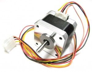
Monday, April 9th, 2012 Stepper motors are used in all kinds of awesome devices (like most of the CNC machines I love to use) but on the surface their inner workings can seem pretty complicated. There are several different ways to make stepper motors (and the mechanical bits of most look reasonably complicated), multiple ways to wire them up, many ways to drive the coils, and a few different sequences that you can fire the coils in. There are several different circuits and controllers out there to drive stepper motors, each with their own advantages and disadvantages with many having different methods of telling the motors what to do. Where do you even start trying to figure out how these things work and how to make them do what you want?
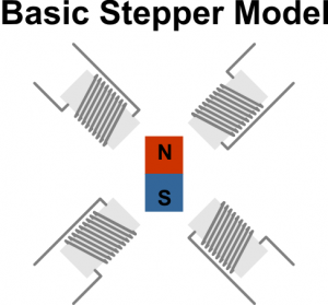
If you can look past all the technical implementation details, the motors themselves are actually not that hard to understand if you're familiar with how magnets and electromagnets work. Once you've got a grasp of what's going on under the hood, you should be able to work backward and start deciphering all the technical stuff. Let's start off our exploration of the inner workings of the typical stepper motor with the simplified model of the thing that I'm going to use to explain how steppers work:
This simple model of one type of stepper is just a single rotatable permanent magnet surrounded by 4 coils. In this model the coils, electromagnets really, are stationary, forming what is called the stator of the motor. The magnet can rotate in place and is attached to the output shaft and these two together form the moving part, or rotor of the motor. There are many ways to build steppers that don't actually look like this inside (in fact most don't look like this) but the idea behind all of them is the same, have a rotor that moves around when you put it near a magnetic field and some coils that are fixed in place that you can turn on and off to move that rotor in a controlled way. Seems simple enough so far? Well then let's dive into wiring this model up!
Unipolar Wiring
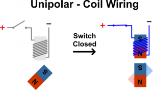
So how do we make this thing move the way we want? First off, lets attach a switch and some power to one of the coils. In this simple setup when the switch is pressed one of the coils turns on and the magnetic field it generates attracts the magnet:
Imagine this same switch setup is attached to each coil of our stepper model. This wiring scheme is called unipolar configuration (more on this later). If you switch on one coil at a time, and each coil you turn on is next to the last one, the magnet will move to a new position each time you turn on the next coil in the sequence:
Depending on the order you power the coils in, you can make the magnet turn clockwise or counter-clockwise. You also know that with every coil switch you make, the magnet will only turn one quarter turn. This known amount of rotation (a quarter turn in our model) for one change in the coil configuration is called a step, and how stepper motors get their name. Each time we power on the next coil in the sequence and shut off the previous one in the sequence, we take a step. Our model has to make 4 steps to go all the way around so we say it has 4 steps per revolution or 90 degrees per step. The resolution of a stepper can be expressed in either degrees of rotation per step or the number of steps to make a single rotation and you can go back and forth by doing a little math (in this case 360/4 steps per revolution = 90 degrees a step, or 360/90 degrees per step = 4 steps per revolution). It's important to note that stepper motors aren't limited to 4 sets per revolution like our model but are generally manufactured with a much higher number of steps per revolution. For example, a common stepper motor might have 200 steps per revolution or 1.8 degrees per step.
So at this point in our understanding of the model we have a motor that we can make move one direction or another and we know exactly how far it has turned by how many times you've switched coils on and off, or stepped. That's pretty much all you can do with a stepper motor, move a known distance in a particular direction. So what else is there to know about controlling the thing?
As you might have guessed, a lot actually! Switching on one coil at a time with a single switch is called unipolar wave drive and is just one of 8 ways to wire up and drive the coils of a stepper motor. All other methods are basically just slightly different ways of doing the same thing we've already done (switch on coils in sequence to make the motor move), but each has its own advantages and disadvantages. Let's look at some other ways to drive the coils:
Well, assuming we've still got only one switch attached to each coil, we could turn on two side by side coils at a time instead of just one. This generates a stronger magnetic field and the magnet moves to somewhere in between the two powered on magnets. To make a step now, we leave one coil on, shut off one, and turn on the next one in the sequence. Each step is still 90 degrees, but now that we've got two coils on at once we've got a stronger magnetic field and our motor is a little more powerful. This is called unipolar full stepping. The only down side is that since we have two coils on at once rather than just one, our motor consumes more power. Let's look at one more unipolar driving sequence:
Now you may have noticed that our magnet was oriented a little differently when we did full stepping. It still moved 90 degrees, but it was about half a step (45 degrees in this case) offset from the positions it was in when using wave drive. We can actually combine our full and wave stepping sequences to get the sequence above. Here two coils are turned on, then only a single coil is, then two again. You'll notice that after 4 steps of this sequence the magnet has only made it half way around and that each step is now only 45 degrees. This sequencing is called half-stepping and it allows you to double the effective resolution of your stepper. The down side here is that the sequencing is a little more complex and your stepper is less powerful every other step because you're only turning on one coil every other step.
Bipolar Wiring
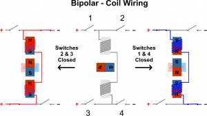
Now let's imagine we wire up the coils a little differently. A single switch for every coil means that the magnetic field of each individual coil can only have one polarity. Because the polarity of the power to the coil never changes, making this setup unipolar (see, I totally told you we'd cover that later). If you take an electromagnet and reverse the polarity of the power you apply to it you'll change the polarity of the magnetic field it generates. To do this with our coils we'll need to add a few more switches:
If we add 3 more switches, we can change the polarity by closing a set of 2 switches to apply power one way and close another set of two switches to apply power the other way. This type of circuit is fairly common and is called an H-bridge because of its shape (read more about them ). Now that we can change the polarity we can also connect opposite coils together and still make the magnet turn all the way around (we'll see how this works in a second). Imagine that our model is now wired up such that the two sets of opposite coils are both wired up like the coils in the picture above, so now we've got 2 connected sets of coils controlled by 8 switches. This is the standard bipolar wiring scheme (bipolar because we can switch the polarity of each of the 2 sets of coils). This setup is harder to control and consumes more power that the unipolar setup but has a few advantages, the main one being that you can get more power out of the motor with this wiring setup than you can the unipolar setup on the same stepper motor.
Now let's look at how we would make this new setup move:
The above sequencing is the bipolar wave drive sequence. We've still got a 90 degree step like the unipolar wave and full stepping drive but two opposite coils are powered at once and these coils flip polarity as they turn the magnet one full rotation. Up next is the bipolar full stepping sequence:
Here all coils are powered all the time! Just like the unipolar full stepping sequence, the magnet settles at a half step in between the two sets of powered coils as it moves around. Since all 4 coils are powered, this setup is the strongest, or highest torque, stepper control setup for a given stepper but since all coils are on all the time, this setup requires the most power. Let's look at one final bipolar sequence, the half-stepping sequence:
Just like the unipolar wiring setup, we can combine the wave and full stepping sequences to create a half-stepping sequence where each step is only 45 degrees. Remember from the unipolar half-stepping sequence though that this method makes every other step a little less powerful because not all coils are powered on each step.
What's Next
There's still plenty to learn about using stepper motors but at this point you should have a pretty good grasp of the unipolar and bipolar wiring schemes and the different sequencing you can use with each to make the motors move. You don't need to know all this stuff to actually dive in and start using stepper motors in your projects because driver chips and software often do a lot of the work for you, but it's always nice to know what's going on behind the scenes, especially if you're trying to track down problems. I'll go into different driving circuitry, micro-stepping, and using various stepper controllers in another post, but in the mean time, here's some additional info on steppers if you want to learn a bit more about how they're constructed and how to use them:
- Good background info on steppers
- Another good intro to stepper motors
- Tutorials with a lot of additional info on steppers and controlling them including current limiting and micro-stepping
- Some good links to info on stepper motors


