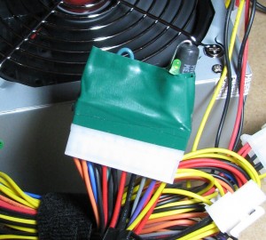
Here's a pic of a quick little dongle I threw together that allows you to power up a PC power supply and use it as a bench supply, or in my case, to power a few stepper controllers for my CNC setup. You can also use the dongle to test potentially bad ATX power supplies.
You can find tutorials on using ATX power supplies outside of PCs all over the net but all of them are pretty much a variant of what I have here. To get the thing up and running, you just need to:
- Connect the green wire on the 20 or 24 pin connector to ground to power on the supply.
- You'll probably want to supply a load to the supply to keep it up and running, usually just a power resistor on the 5V rail, a 10 Ohm 10W resistor is typically used, creating a 2.5W load. I've also seen people simply plug in an old PC peripheral like a hard drive to the supply to provide this load as well.
- Attach an LED to the output of the supply OK signal to get a nice "everything's fine" light.
Here's what you'll need:
- 30 Ohm 5W Resistor - Mouser P/N: - This puts a nice 0.83W load on the 5V rail. Don't worry if this warms up a little bit during operation, that's what a resistive load does. This smaller load seems to work fine for me.
- 20-Pin Power Supply Connector - Mouser P/N: - Just the socket we need to connect to the ATX supply where a standard motherboard would be connected.
- 330 Ohm 1/4W Resistor - Just a current limiting resistor, not needed if you don't put a power on light on your dongle.
- Green LED - Just a typical LED for your power good light.
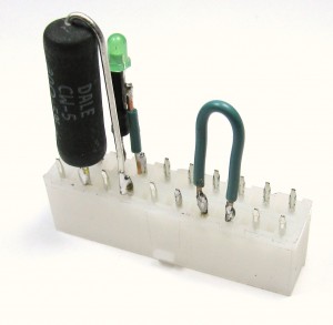
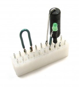
Here's a couple close up shots of the dongle on the inside:
Check out the Wikipedia entry for and scroll down to the power supply section for a detailed pinout of the ATX connector. Note that I'm using a 20-pin connector and the connector pin numbers on the Wikipedia article are for a 24-pin. I'm using the pin numbers from the article, so realize they could be different based on which connector's pinout you're looking up, so pay attention to the actual signal names!
Basically I've connected pin 16 (power on) to pin 15 (ground), put a 30 Ohm resistor across pin 21 (+5V) and 19 (ground), making sure that the long exposed lead is connected to ground, and connected the positive lead of my indicator LED through a 330 Ohm resistor (hidden in the heat shrink) to pin 8 (power good) and the negative lead to pin 7 (ground). After testing, I wrapped the whole thing in a little electrical tape and installed it. I'm using the switch on the back of the power supply as my power switch, but if you want to have a more convenient switch wired to your dongle, just replace the jumper between ground an power on with a standard normally open switch.
Tags: CNC


