Archive for the ‘Tutorial’ Category

Quick Projects – Building a CNC Mill Stand and Enclosure

Saturday, December 25th, 2010

Time for another quick project.  This time it's a cheap, simple CNC mini-mill enclosure using materials I had readily available, a re-purposed parts washer, and a combination of two of man's greatest inventions, duck tape and cardboard!  Well, not really cardboard, but corrugated plastic called coroplast only because cardboard isn't exactly waterproof.

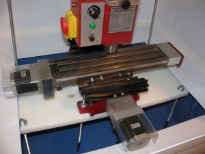
To provide some background, I picked up a CNC converted X2 mini-mill from a local hobbyist a few weeks ago so I could try my hand at making some metal stuff.  It came with a DIY wood stand that was a little bigger than I would have liked, a slightly leaky PVC/wood/expanded foam flood system, and an open front that didn't stop little bits of metal from flying out and on to the floor.   I wanted to build a new stand and enclosure that I could use a flood system with and that was fully enclosed so I could use it inside without having to worry about clean up.

I found a build I really liked that I wanted to do here.  Basically, the idea is to set the mill in a cheap parts washer and create a cheap enclosure to set on top.   Just like the stock shelving project, I tried to make the most of a single sheet of material, so I tried to set a hard limit of using only one sheet of coroplast to complete this project.  Here's a list of all the stuff needed to make a full enclosure:

  • Harbor Freight 20-Gallon Parts Washer - Wait till it's on sale, I got mine for $70
  • 1 4'x8' sheet of 4mm coroplast in the color of your choice - I got mine at Lair Plastics in KC for about $10
  • 1 or 2 60yd rolls colored duck tape - I think you can get away with a single roll if you're careful, but I had to start another roll to finish out the project
  • 4'-5' of 1" wide 1/8" steel bar - this will be used to support the enclosure
  • 6 small magnets - To fix the steel bar to the parts washer
  • 28"x32" sheet of 0.118 acrylic - I got this for free from someone, I assume it's a standard size at some hardware stores
  • 1 drawer handle to attach to the acrylic sheet

Build the Stand

Start off by by assembling the parts washer and removing the parts you won't be using.  Be careful when removing the lid lift hardware, there's a spring in there that popped out when I was removing it that looked like it would hurt quite a bit if it hit you.  There's also a square hole in the side of the parts washer bin for the pump that comes with the stand.  You'll probably want to block that off with a few strips of duck tape, or maybe a big sheet magnet if you want something that will be easier to remove in the future.

Next you'll need to build something to set your mill on inside the wash tub.  What you set the mill on will probably depend on what you have on hand, but I used a 12"x24" sheet of 3/4" HDPE with eight 3/8" threaded rod stand offs that were coated with plasti-dip on one end so that they didn't scratch the bottom of the parts bin.  I left two of these threaded rod sections longer so I could mount additional hardware (cable management, flood nozzles, lights) inside the enclosure later.

Build the Enclosure

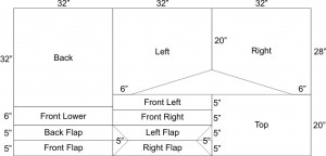
Next, you'll need to cut all the parts you'll need out of your coroplast sheet.  My sheet was not exactly 48 inches by 96 inches, so make sure you measure the size of your stock beforehand.

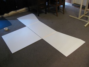
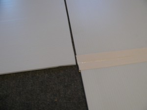
After you've cut all your pieces out, find some space to work and start seeming things up with your duck tape.  It's best to leave a little bit of a gap between pieces at this point because you'll want them to fold easily.  There's no set pattern here in terms of what get's seamed up first, just do what you think is logical.  If you mess up, in most cases you can just pull the tape off and start over.

Along the way you'll probably want to cover any exposed sections of the internal comb with tape to prevent debris and liquid from finding their way in there.

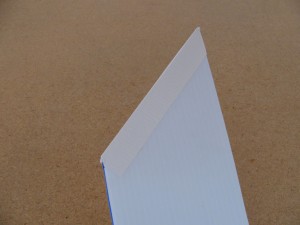
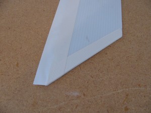
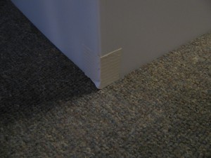
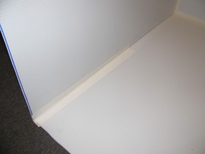
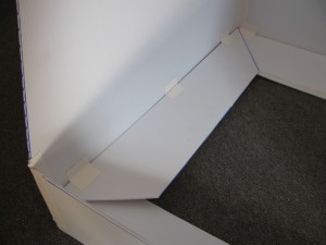
After the top, back, and sides are in place, take the 4 triangular pieces you cut out of the left and right flaps and tape them into the bottom corners.  I also took some of the scrap and added triangles to the front of the enclosure because the top was sagging and I ended up leaving them in place.  Install the front and back flaps first and attach them about 2" from the bottom of the enclosure.  After the front and back flaps are in place, install the left and right ones.  Here's a picture of the left flap just before installation:

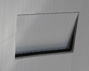
After the flaps are in place, you'll want to route your cabling.  I did this by cutting a flap in the back of the enclosure.  I cut only half way through the top of the flap (which is much easier to do "against the grain" of the coroplast) and folded it inward.

Lastly, take your acrylic sheet and tape it in place along the top.  Remember to tape up both sides.

Bringing it all Together

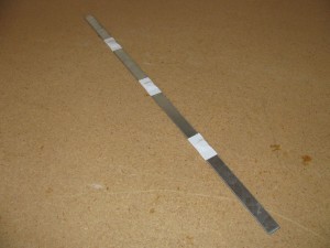
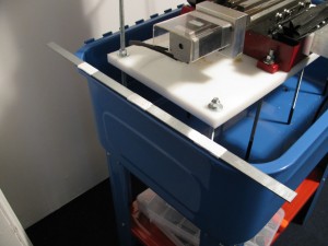
One last minute addition to construction was adding some metal rails attached to the stand with magnets to support the whole enclosure when it was completed.  The corners on the bottom of the enclosure rest on these rails and support the entire enclosure.  Ideally, these rails would be 28" wide but I only had a 48" strip of steel to work with, so both of mine are 24".  I taped three 1/2" rare earth magnets to each, approximately 6" apart.

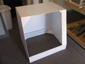
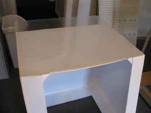
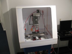
After the  rails are in place, simply fold all the flaps on the enclosure up and slide it over the top of your mill that's already in place inside the parts washer basin.   Fold down the front and back flaps then the side flaps and shift the enclosure into place.  Here's a shot of the inside of my enclosure once it was in place with the flaps down:

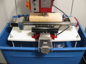
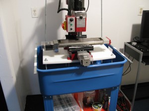
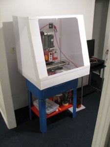
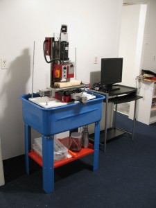
And here's a picture of the entire enclosure and stand when finished:

Construction Tips

Tack sections that you're taping together with a small square of tape to make things go more smoothly.

Internal seems can be tricky, so you may want to do them in two or more strips.

When sizing up the flaps, I tacked them in with 3 squares of tape and tried them out.  You may want to do this in your setup to make sure everything's looking good before taping everything down.

Final Thoughts

Overall I think this enclosure will work well for the time being, and it's not bad for under $100 total to construct.  I think the Z and X axes may end up bumping the enclosure, but only toward their extremes.  One thing I did notice about the white coroplast is that the oil I use to keep the machine lubricated seems to permanently discolor it.  Not a huge deal really.  It'll probably be a bit before I get around to getting the flood system up and running, and I'll probably make some modifications to the setup when I get to that, but I'm anxious to see how well everything works when I'm splashing cutting fluid around inside.
Share

Quick Projects – Hard Drive External Hard Drive Enclosure

Sunday, December 19th, 2010

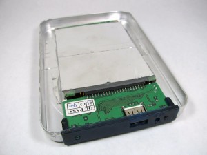
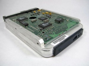
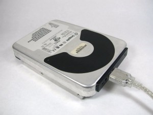
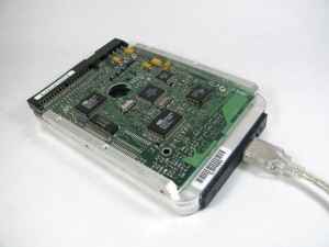
I thought I'd share a project I think is simple but pretty awesome none the less.  Several years ago I picked up an external USB 2.5" hard drive enclosure to use with a laptop hard drive I picked up while dumpster diving.  The hard drive was a bit too tall for the enclosure that came with the controller so I had to improvise.  I had several other 3.5" drives pulled from various systems I had stripped hanging around, and it looked like the controller and 2.5" hard drive would fit inside one if I found the right drive.

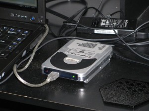
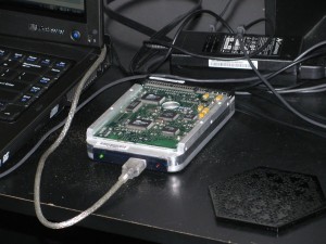
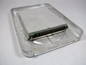
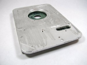
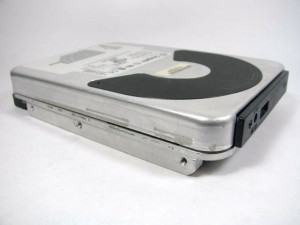
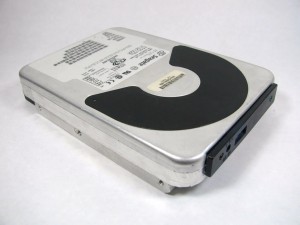
After some searching and disassembling some drives, I found an old 2GB Seagate ST32122A drive that looked like it would work for my enclosure.  After removing all the platters and other internal components, I removed the drive lid and carefully cut two slits in it with tin snips.  I folded the flap I created back carefully by hand, trying not to bend the top of the lid as I did so.  I cut a small square of PETG out of a blister back to protect the PCB on the back of the 2.5" hard drive and taped the drive in place with aluminum faced tape.  You can see the PETG sheet sticking out from underneath the tape in the pictures below.

When I was building this originally, I wanted the top and bottom of the enclosure to nest perfectly, so I milled down the bottom section with a Dremel.  I eventually decided that it wasn't worth the effort and that no one will notice that the front of the enclosure is a little under 1/16" taller than the back.

After getting the hard drive and controller in place, I put the top and bottom back together and sealed them with a 1/4"-3/8" strip of aluminum tape and the enclosure was complete.

The original drive was a 6GB and I've since upgraded it to an 80GB drive and will probably upgrade it again if I run across a cheap PATA 2.5" in the future.

Share

Cricut Direct PC Control Working!

Monday, August 16th, 2010

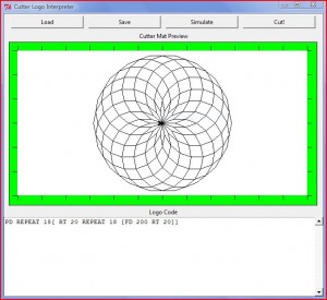
After a bit of work and help from fellow Hackerspace members, we managed to figure out how to talk to the Cricut.  Check out the Cricut Wiki I started for more details on the protocol and check out the libcutter project on GitHub if you want to start writing your own control software.  Libcutter's goal is to be a nice cross platform library for controlling the Cricut and potentially other similar devices.  Right now all our experimentation has been with Cricut personals at firmware revision 1.34, but I'm hoping it'll work with other models as well.  I coded up a quick Python demo script that's a Logo interpreter for the Cricut that's included with libcutter.  Here's a quick video of it in action:

I've also got a quick Windows only Python module implementation that you can use to control the Cricut as well.  To get everything up and running, you'll need to get Python and PyUSB installed and grab this nice Python XXTEA implementation.  After that, just download the Cricut protocol module and the Logo demo script and you should be ready to draw (or cut) your favorite Hackerspace logo, or perhaps a hole bunch of circles:

You can of course write your own control programs to do other equally useless but still fun things:

Share

Using a PC Joystick with the Arduino

Thursday, September 10th, 2009

I didn’t find any tutorials on how to use a standard PC joysticks/gamepads with the Arduino directly (someone correct me if I’m wrong), so I thought I’d take this opportunity to write one.  These input devices can make controlling your projects easy and there are a few controller schemes you can choose from rather than being locked down to a standard game controller (as awesome as the NES controller is, it’s not ideal for all projects) or having to make your own entirely from scratch.  Interfacing with these old devices is pretty easy as well since you don't need to decipher any protocol to communicate with them and you can generally figure out what's going on with them with just a simple multimeter.  I use an old joystick that I’ve held on to for use with various projects to control the Labywiinth for debug and when we don’t have a PC set up to relay Bluetooth through.

PC Joystick

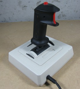
I should clarify here that the PC joysticks/gamepads I’m referring to here are the old school PC joysticks have a 15-pin D-sub connector rather than USB.  These are readily available in a number of places and are generally very cheap (most thrift stores I’ve been in have them for under $5).  If they don’t have tons of features, like more than 4 buttons and 4-axis control, they’ll most likely just be a few potentiometers and buttons wired up in the standard joystick port configuration.  You can find a good write up on the PC joystick port here including a history of the interface (and some info on circuits here).  It's also worth noting that if you want to use a more advanced joystick with your project and don’t need a stand alone solution, you can always use a PC to relay input from that joystick to the Arduino as described here, but I really like being able to plug straight into the Arduino in most cases.

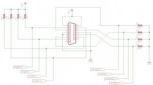
It is pretty straight forward to create a dongle to connect any of these old school interface devices to your Arduino.  First off, you’ll need a 15-pin female D-Sub connector (preferably with solder cups for ease of construction), which you can get from old PC riser cards (486 or older generally) or a quick Digikey search will reveal that a cheap one can be had for a whopping $1.33.   You can also cut up an old 15-pin cable extender if you happen to come across one.  Next, for each axis you’ll need a resistor to create a voltage divider and for each button you’ll need a resistor to use as a pull up (more on each of these later).  I used 100K Ohm resistors for the voltage dividers to measure the X-axis and Y-axis potentiometers and 10K Ohm resistors should be sufficient for pull up resistors for your buttons.  Here’s what the resulting circuit would look like if you wired up all the available buttons and potentiometers:

Joystick Dongle Schematic

Joystick Dongle Schematic

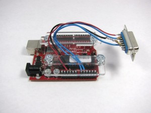
I suggest only wiring up the inputs you’re interested in as I did (in my case, just the X-axis and Y-axis):

Arduino Joystick Setup

I used a wiring harness “shield” so I don’t accidentally rip out my jumper wires while using the joystick.

If you’re familiar with potentiometers through other experiments with your Arduino (or other microcontrollers) where you hook up a potentiometer and read the voltage on the wiper with the ADC, you may be wondering why we need to use another resistor to measure the potentiometers in the joystick. The answer is, if you look at the schematic of a joystick you’ll notice that only two of the terminals of the potentiometer are wired up.  The way you would normally read the position of a potentiometer on the Arduino is to hook up the two outside terminals of the potentiometer to +5V (or whatever voltage you’re operating at) and ground and connect the wiper of the potentiometer to one of the analog channels and read the voltage at the wiper terminal. The reason this works is because the entire potentiometer acts as a voltage divider with current flowing through the two outside terminals.  The location of the wiper is basically where the two resistors in the voltage divider are split, and the total resistance of these two resistors is always the value of the potentiometer (just because of the way the potentiometer is constructed).

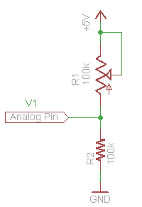
To read the joystick potentiometer, we’ll need to set up our own voltage divider with a 100K Ohm resistor:

Basic Voltage Divider Circuit for Reading a Potentiometer

Basic Voltage Divider Circuit for Reading a Potentiometer

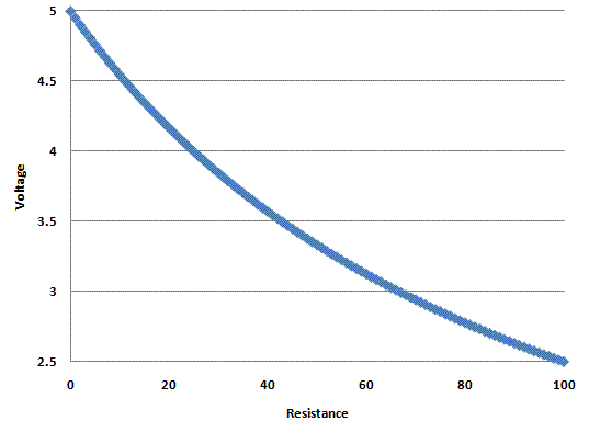
This is the same circuit that is wired up to each potentiometer in the dongle schematic, I've just shown the potentiometer inside the joystick for clearity. If we graph out the voltage we would measure as we varied the 100K potentiometer in the joystick, it would look something like this:

Voltage vs Resistance

You'll notice that, while close, this relationship isn't linear.  If we want to go from this measured voltage to the actual resistance of the potentiometer in the joystick (which is a presumably linear indicator of the actual position of the potentiometer) we can apply Ohm’s law and solve for R1 in our voltage divider circuit.  When we’re done we end up with the following equation:

R1 = 500/V1 – 100

Where R1 is the resistance in K Ohms and V1 is the measured voltage in volts.  This is all well and good if we’re measuring the voltage with a multimeter, but since the Arduino reports measured voltage as an integer on a scale from 0-1023, we need to scale our equation:

R1 = 102300/V1 - 100

Now we can plug in the raw value read from the ADC and we’ll get an integer value from 0-100 that should correspond to the position of the joystick on that axis.  I needed to adjust the range a bit for the Labywiinth project so that the position of the joystick was mapped to 0-180 with 90 being the center.  To do this you could multiply the result by 1.8 but this will require a floating point operation or some additional integer operations to do properly.  It’s simpler to just modify our equation a bit to get the range we want:

1.8 *(102300/V1 - 100) = 184140/V1 – 180

Here’s some sample Arduino code that reads the position of a joystick who's X-axis and Y-axis are connected to ANALOG0 and ANALOG1, respectively, and reports the resistance (position) of each axis back over the serial connection:

void setup() {
Serial.begin(9600);
}

void loop () {
long x, y;
int x_in, y_in;

x_in = analogRead(0);
y_in = analogRead(1);


if (x_in)
x = 102300/x_in - 100;
else
x = -1; //this should only happen if the joystick isn't connected
if (y_in)
y = 102300/y_in - 100;
else
y = -1; //this should only happen if the joystick isn't connected

Serial.print("X: ");
Serial.print(x, DEC);

Serial.print("   Y: ");
Serial.print(y, DEC);

Serial.println("");
}

As far as using the buttons on the joystick or game pad go, just treat them as a regular button, but remember that it's wired up to be active low (you'll read a 0 on the pin the button is connected to when it's pressed and a 1 when it's not).  There's a simple example for using a button as an input on the Arduino site.  The main reason to hook up the buttons to be active low is because some joysticks and game pads have circuits that are powered off of the ground pins that are used for the buttons and the +5V pins that are used for the potentiometers.  Most often this circuitry is used to implement some "turbo" functionality were the controller itself quickly toggles a button when it is pressed and held.  I've tested one controller that I happened to have on hand that had a "turbo" mode and it worked properly with the above dongle circuit.

So that's it!  You should now be able to put some old joysticks or game pads to work in your upcoming Arduino projects.  Feel free to post any additional questions you might have and/or corrections I should make to the comments.

Share