I didn’t find any tutorials on how to use a standard PC joysticks/gamepads with the Arduino directly (someone correct me if I’m wrong), so I thought I’d take this opportunity to write one. These input devices can make controlling your projects easy and there are a few controller schemes you can choose from rather than being locked down to a standard game controller (as awesome as the NES controller is, it’s not ideal for all projects) or having to make your own entirely from scratch. Interfacing with these old devices is pretty easy as well since you don't need to decipher any protocol to communicate with them and you can generally figure out what's going on with them with just a simple multimeter. I use an old joystick that I’ve held on to for use with various projects to control the Labywiinth for debug and when we don’t have a PC set up to relay Bluetooth through.
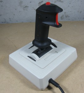
I should clarify here that the PC joysticks/gamepads I’m referring to here are the old school PC joysticks have a 15-pin D-sub connector rather than USB. These are readily available in a number of places and are generally very cheap (most thrift stores I’ve been in have them for under $5). If they don’t have tons of features, like more than 4 buttons and 4-axis control, they’ll most likely just be a few potentiometers and buttons wired up in the standard joystick port configuration. You can find a good write up on the PC joystick port including a history of the interface (and some info on circuits ). It's also worth noting that if you want to use a more advanced joystick with your project and don’t need a stand alone solution, you can always use a PC to relay input from that joystick to the Arduino as described , but I really like being able to plug straight into the Arduino in most cases.
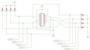
It is pretty straight forward to create a dongle to connect any of these old school interface devices to your Arduino. First off, you’ll need a 15-pin female D-Sub connector (preferably with solder cups for ease of construction), which you can get from old PC riser cards (486 or older generally) or a quick Digikey search will reveal that a can be had for a whopping $1.33. You can also cut up an old 15-pin cable extender if you happen to come across one. Next, for each axis you’ll need a resistor to create a voltage divider and for each button you’ll need a resistor to use as a pull up (more on each of these later). I used 100K Ohm resistors for the voltage dividers to measure the X-axis and Y-axis potentiometers and 10K Ohm resistors should be sufficient for pull up resistors for your buttons. Here’s what the resulting circuit would look like if you wired up all the available buttons and potentiometers:
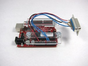
I suggest only wiring up the inputs you’re interested in as I did (in my case, just the X-axis and Y-axis):
I used a wiring harness “” so I don’t accidentally rip out my jumper wires while using the joystick.
If you’re familiar with potentiometers through other with your Arduino (or other microcontrollers) where you hook up a potentiometer and read the voltage on the wiper with the ADC, you may be wondering why we need to use another resistor to measure the potentiometers in the joystick. The answer is, if you look at the schematic of a joystick you’ll notice that only two of the terminals of the potentiometer are wired up. The way you would normally read the position of a potentiometer on the Arduino is to hook up the two outside terminals of the potentiometer to +5V (or whatever voltage you’re operating at) and ground and connect the wiper of the potentiometer to one of the analog channels and read the voltage at the wiper terminal. The reason this works is because the entire potentiometer acts as a with current flowing through the two outside terminals. The location of the wiper is basically where the two resistors in the voltage divider are split, and the total resistance of these two resistors is always the value of the potentiometer (just because of the way the potentiometer is constructed).
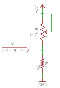
To read the joystick potentiometer, we’ll need to set up our own voltage divider with a 100K Ohm resistor:
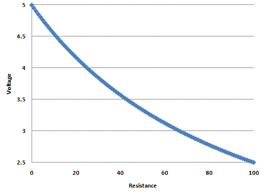
This is the same circuit that is wired up to each potentiometer in the dongle schematic, I've just shown the potentiometer inside the joystick for clearity. If we graph out the voltage we would measure as we varied the 100K potentiometer in the joystick, it would look something like this:
You'll notice that, while close, this relationship isn't linear. If we want to go from this measured voltage to the actual resistance of the potentiometer in the joystick (which is a presumably linear indicator of the actual position of the potentiometer) we can apply and solve for R1 in our voltage divider circuit. When we’re done we end up with the following equation:
R1 = 500/V1 – 100
Where R1 is the resistance in K Ohms and V1 is the measured voltage in volts. This is all well and good if we’re measuring the voltage with a multimeter, but since the Arduino reports measured voltage as an integer on a scale from 0-1023, we need to scale our equation:
R1 = 102300/V1 - 100
Now we can plug in the raw value read from the ADC and we’ll get an integer value from 0-100 that should correspond to the position of the joystick on that axis. I needed to adjust the range a bit for the Labywiinth project so that the position of the joystick was mapped to 0-180 with 90 being the center. To do this you could multiply the result by 1.8 but this will require a floating point operation or some additional integer operations to do properly. It’s simpler to just modify our equation a bit to get the range we want:
1.8 *(102300/V1 - 100) = 184140/V1 – 180
Here’s some sample Arduino code that reads the position of a joystick who's X-axis and Y-axis are connected to ANALOG0 and ANALOG1, respectively, and reports the resistance (position) of each axis back over the serial connection:
void setup() {

Serial.begin(9600);

}
void loop () {

long x, y;

int x_in, y_in;
x_in = analogRead(0);

y_in = analogRead(1);
if (x_in)

x = 102300/x_in - 100;

else

x = -1; //this should only happen if the joystick isn't connected

if (y_in)

y = 102300/y_in - 100;

else

y = -1; //this should only happen if the joystick isn't connected
Serial.print("X: ");

Serial.print(x, DEC);
Serial.print("   Y: ");

Serial.print(y, DEC);
Serial.println("");

}
As far as using the buttons on the joystick or game pad go, just treat them as a regular button, but remember that it's wired up to be active low (you'll read a 0 on the pin the button is connected to when it's pressed and a 1 when it's not). There's a simple example for using a on the Arduino site. The main reason to hook up the buttons to be active low is because some joysticks and game pads have circuits that are powered off of the ground pins that are used for the buttons and the +5V pins that are used for the potentiometers. Most often this circuitry is used to implement some "turbo" functionality were the controller itself quickly toggles a button when it is pressed and held. I've tested one controller that I happened to have on hand that had a "turbo" mode and it worked properly with the above dongle circuit.
So that's it! You should now be able to put some old joysticks or game pads to work in your upcoming Arduino projects. Feel free to post any additional questions you might have and/or corrections I should make to the comments.
