Raspberry Pi Camera Enclosure
Grab a copy of this kit and grab the design files !
Step 1: Remove masking material
Peel off the paper masking from all of the parts

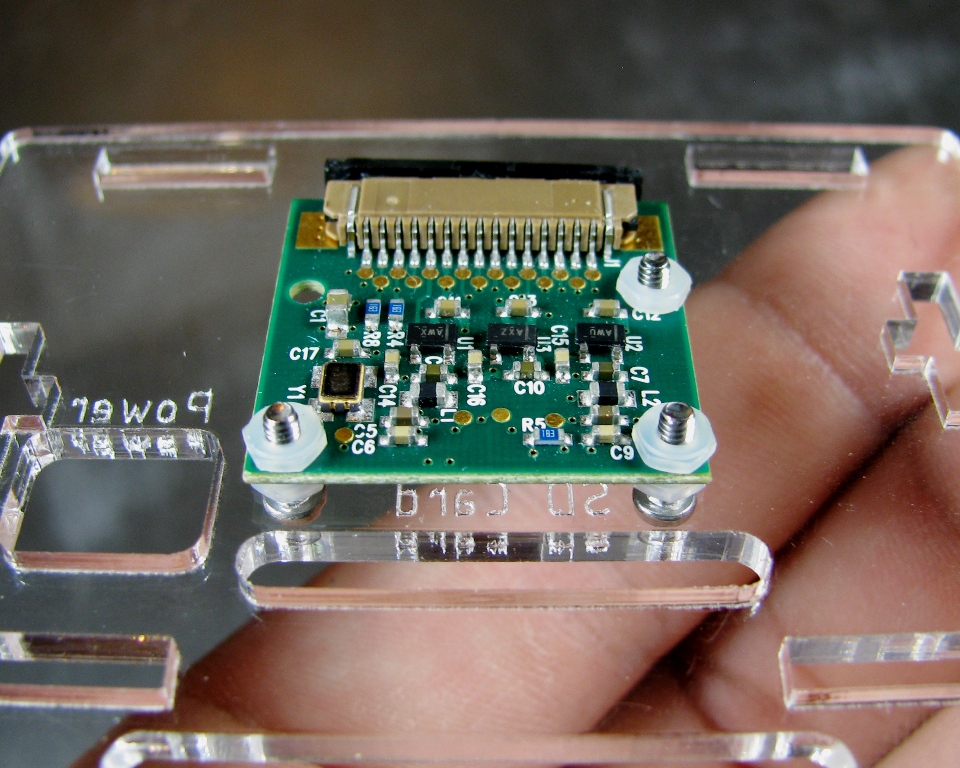
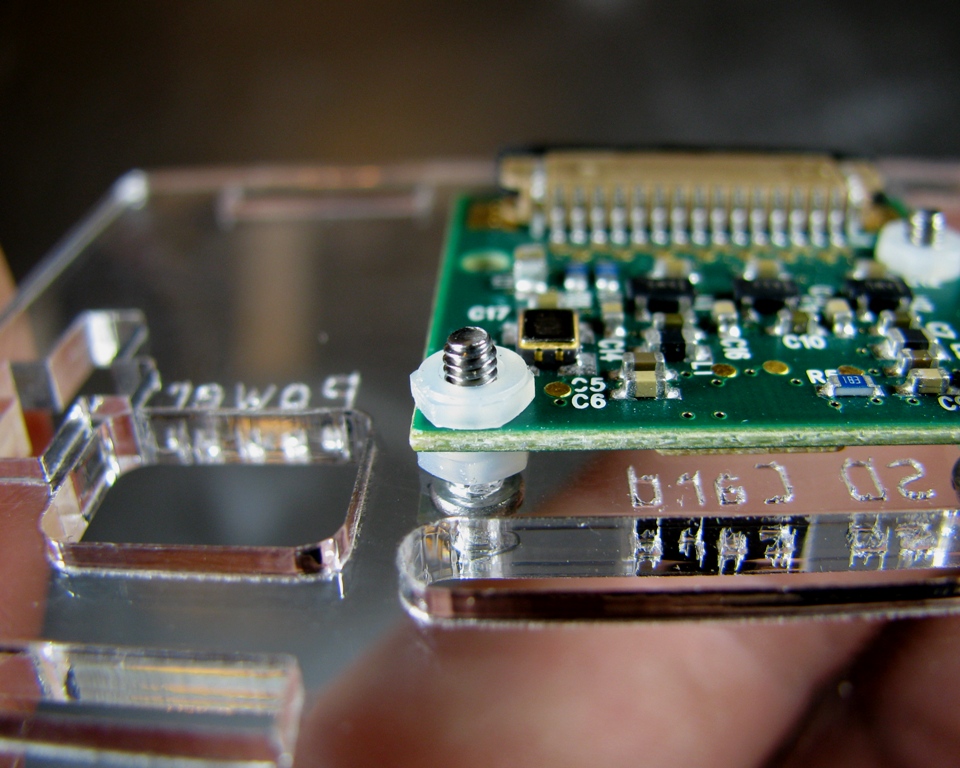
Step 2: Mount the Camera Module
Take the M2 screws and put them in the 3 holes on the camera mount side. Then thread on a nut on each of them. This nut will act as a spacer for your camera module.

Install the camera module and thread on the remaining nuts and tighten them down.
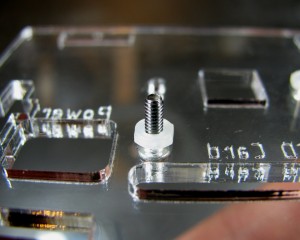
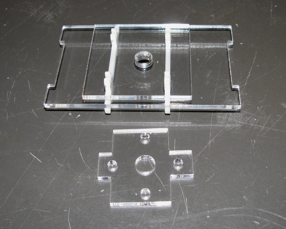
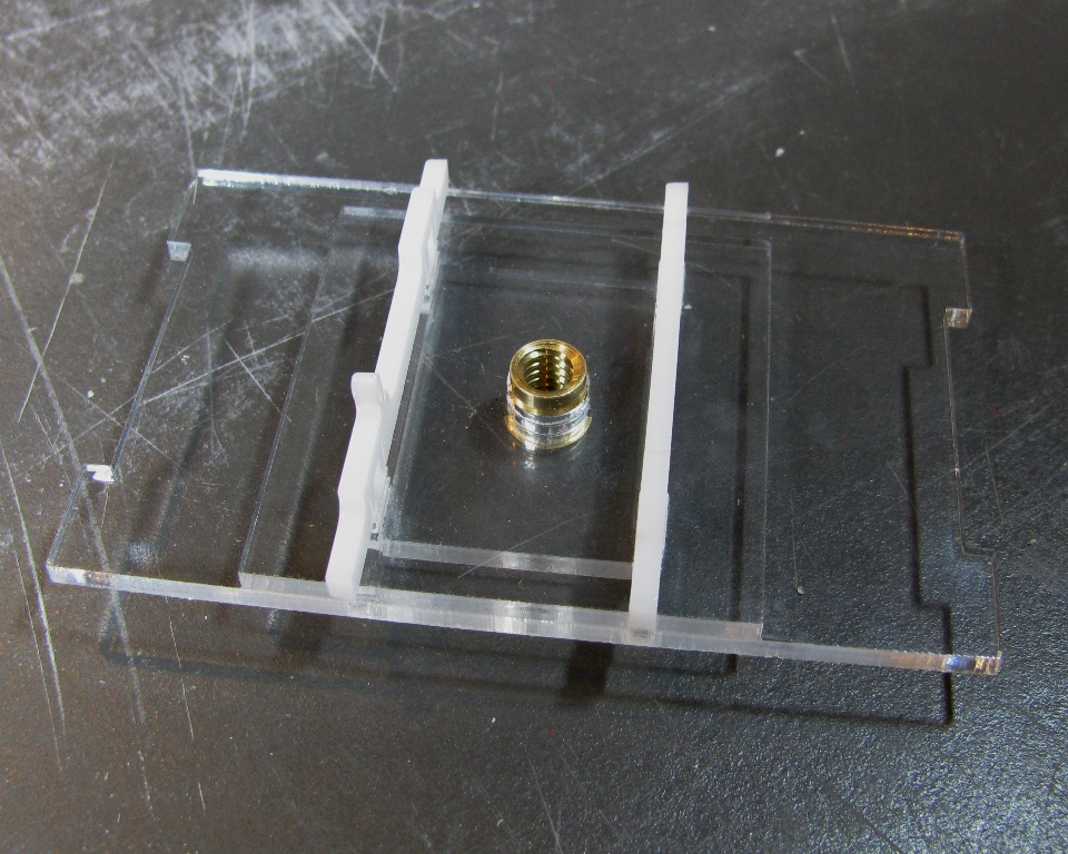
Step 3: Assemble the bottom
Grab the two panels that look like this.
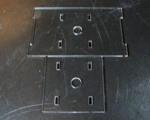
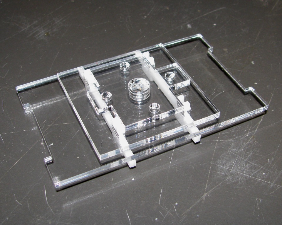
You will notice on the larger of the two panels that the slots are slightly off center. Orientate the panel so that the slots are more towards the left. Stack the larger panel on top of the smaller panel and line the hole and slots up. Now take the PCB mounting clip and snap it into the leftmost pair of slots with the PCB mounting nub closest to you. Snap the other mounting clip in the right pair of slots.

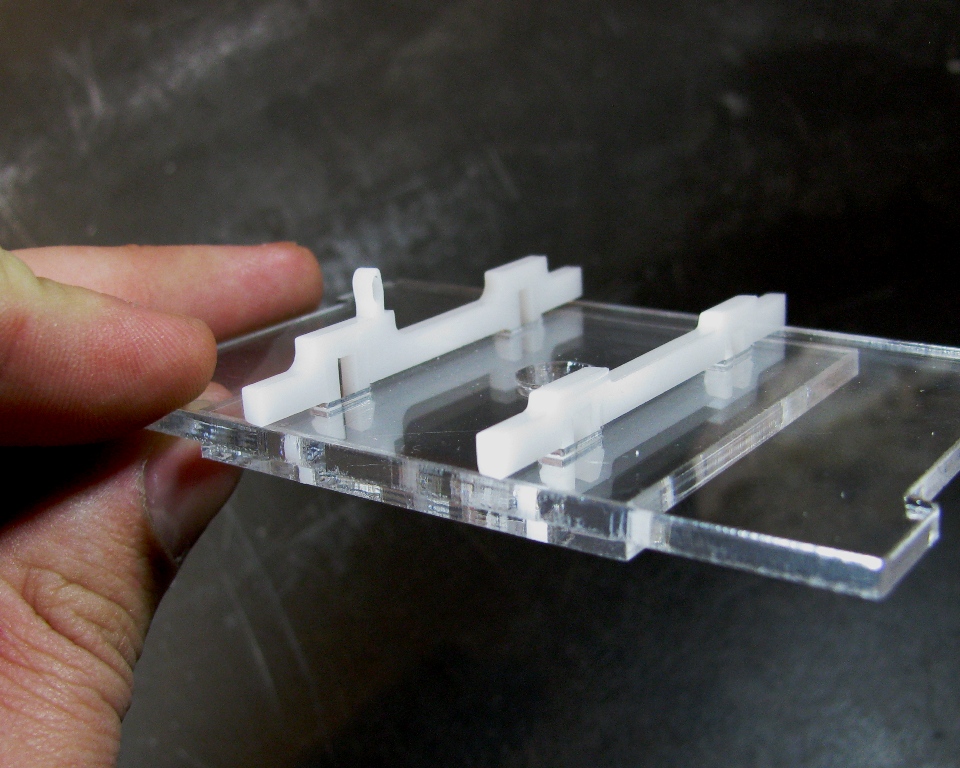
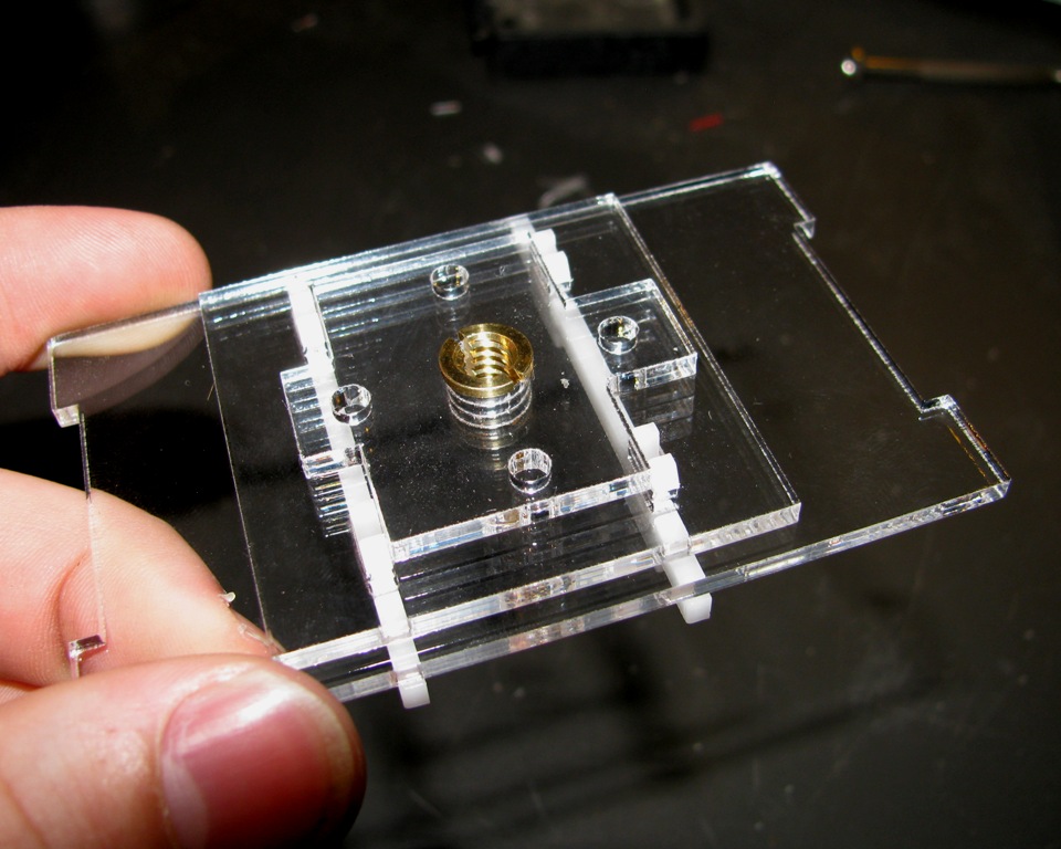
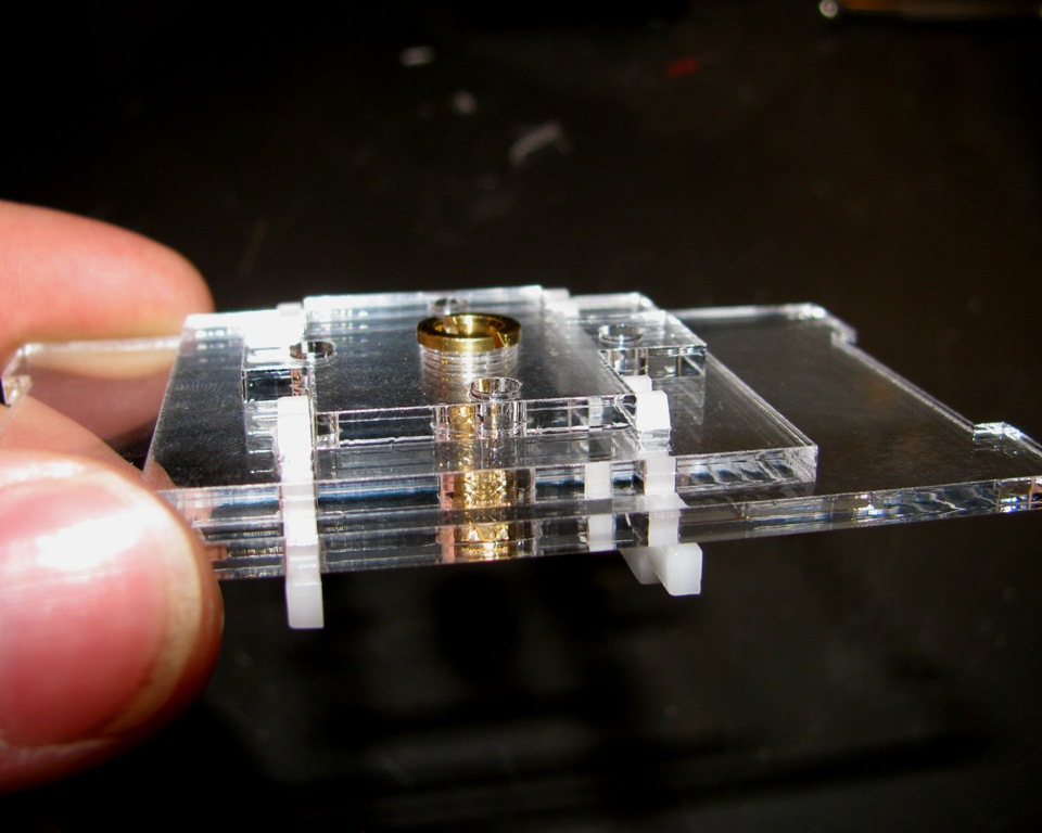
Finally, take the small cross piece and orientate its hole with the hole on the bottom piece and place it between the clips. Now insert the brass fitting as shown.
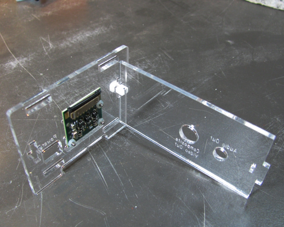
Step 4: Attach Camera/SD Card/Power Side and Composite Out/Audio Out Side Together
Take the Composite Out/Audio Out Side and insert the tab into the slot on the right side of the Camera/SD Card/Power Side. Snap one of the white clips into place to hold the sides together.
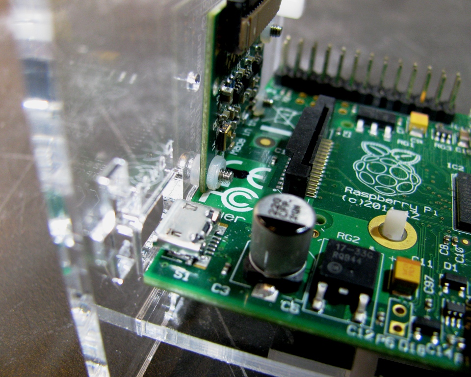
Step 5: Mount the Raspberry Pi on the bottom
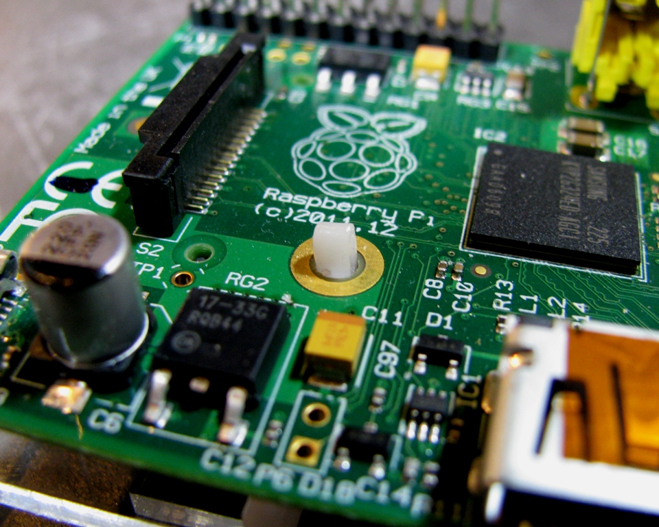
Take the Raspberry Pi and snap it onto the PCB mounting clip.
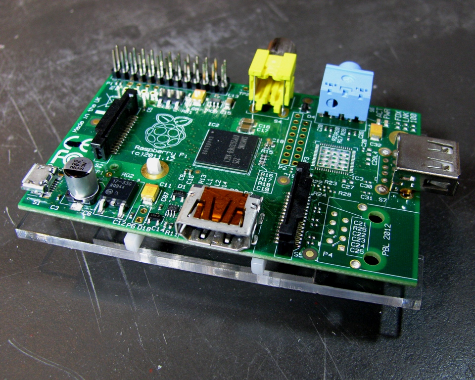
* *Note that a few very early model B boards did not have mounting holes on the boards. If you have one of these early boards, you'll need to clip off the loop (it's fairly easy to do with a pair of flush cutters) before continuing.
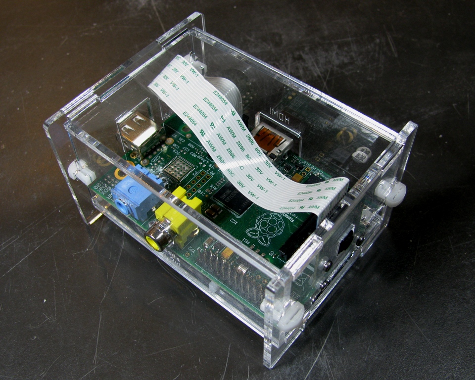
Step 6: Insert the Raspberry Pi into the case
Take the Raspberry Pi and bottom assembly and work it into position with the two assembled sides as shown.
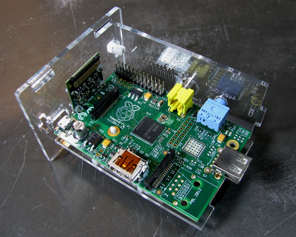
The Raspberry Pi PCB should snug up under the camera module.
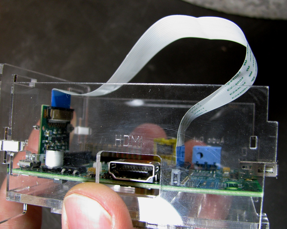
Step 7: Install HDMI Side
Slide the HDMI side into place and snap the clip into the slot. It is best if you squeeze the HDMI and Composite Out/Audio Out sides together in one hand to help prevent the bottom and PCB board from falling out.
Step 8: Install the Camera Ribbon Cable
Lift up the connector locks on both the Camera Module and the Raspberry Pi.
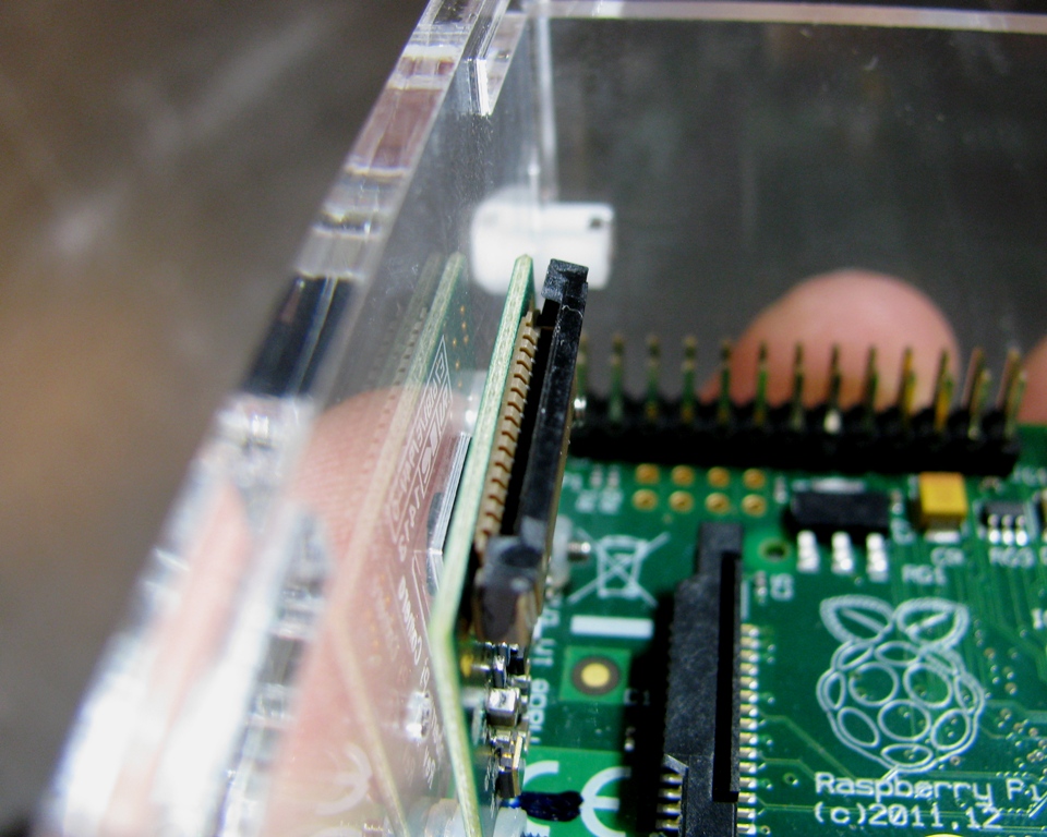
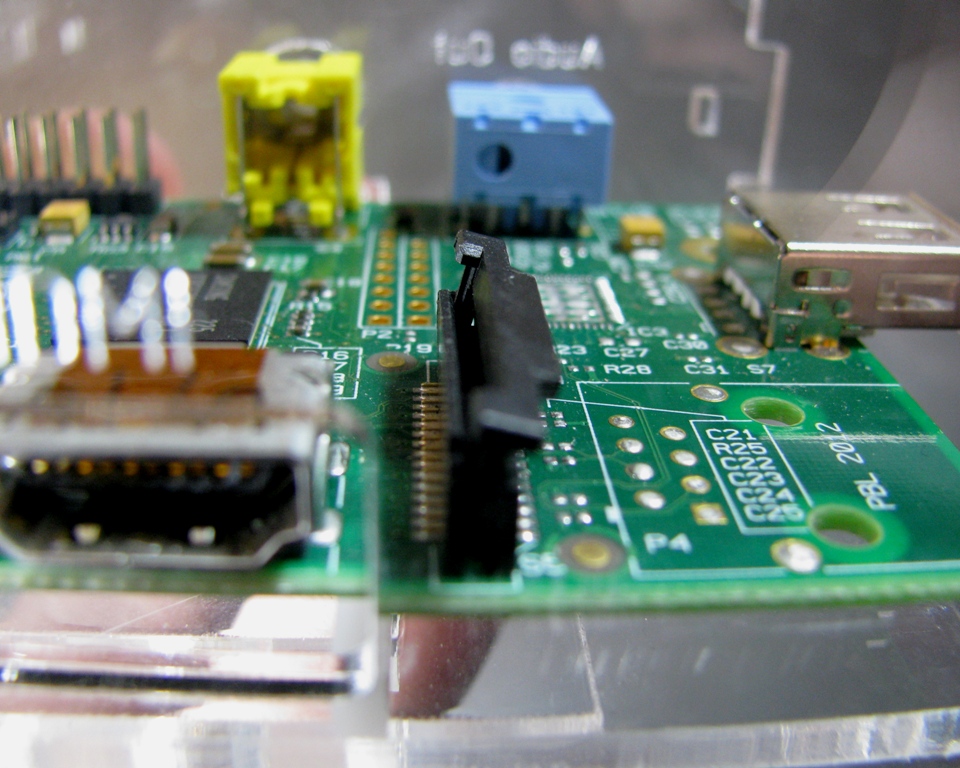
Insert the ribbon cable into the Camera Module connector and lock it in place. Then insert the other end of the ribbon cable into the connector on the Raspberry Pi and lock it in place as well.
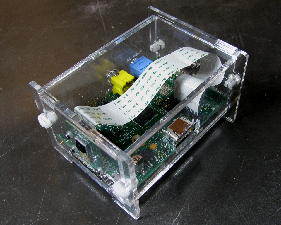
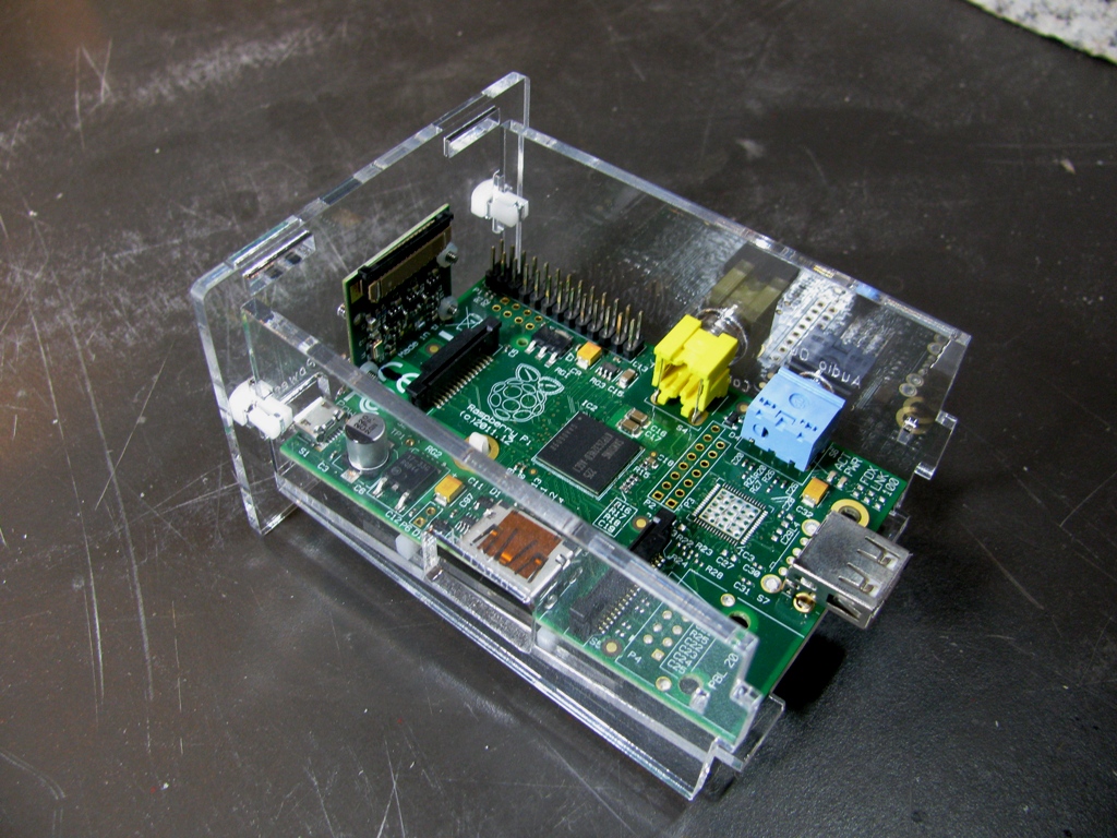
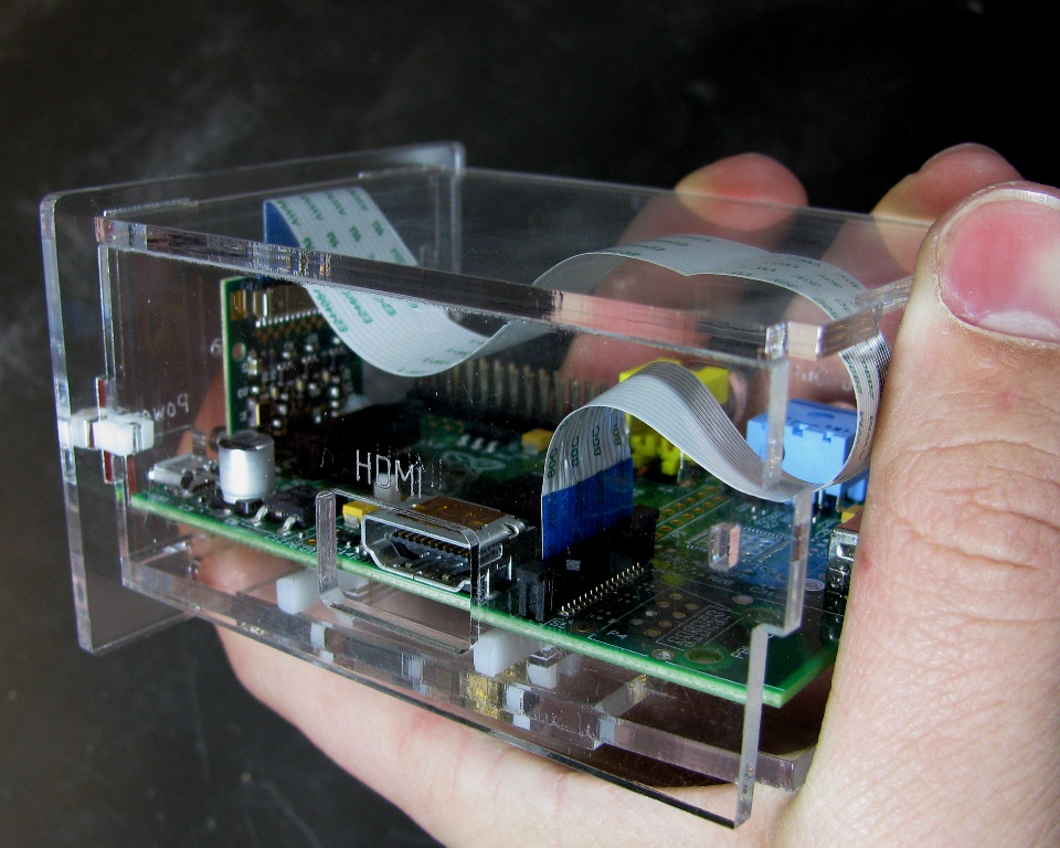
Step 9: Install Top
Set the top on the case and slide the tabs into the SD Card/Power side.
Step 10: Install the Ethernet/USB side
Put the Ethernet/USB side panel in place and insert the clips.
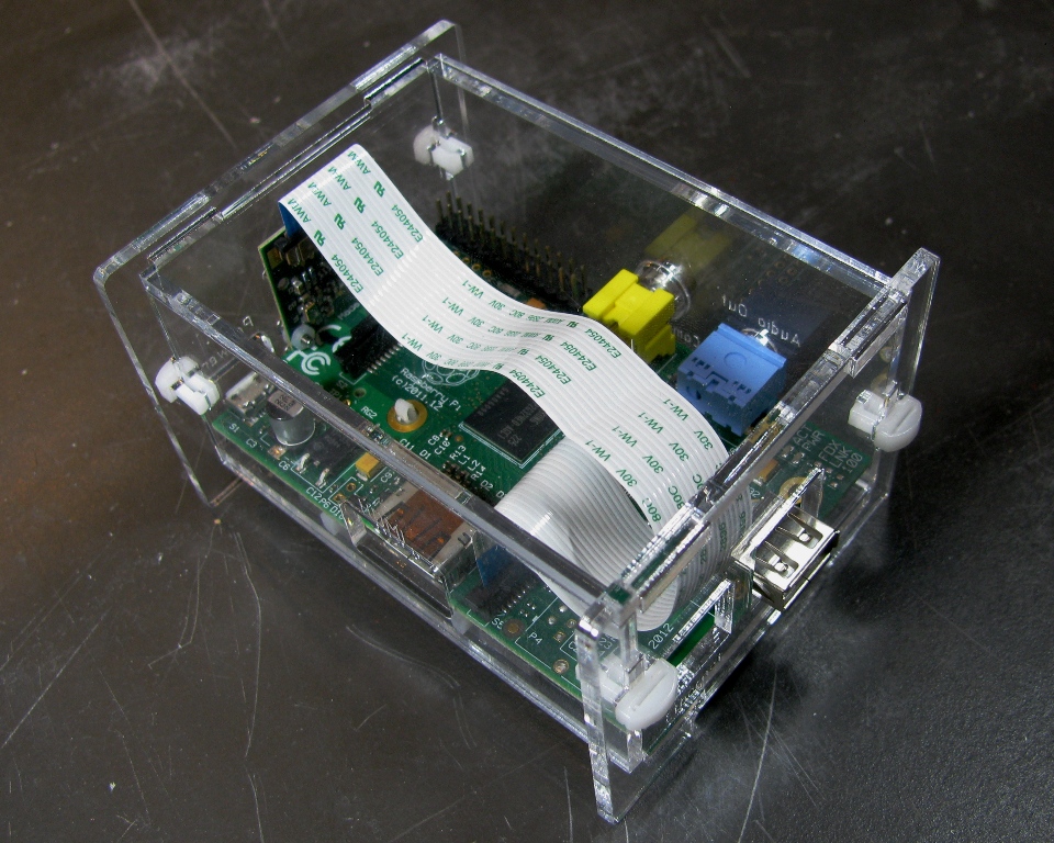
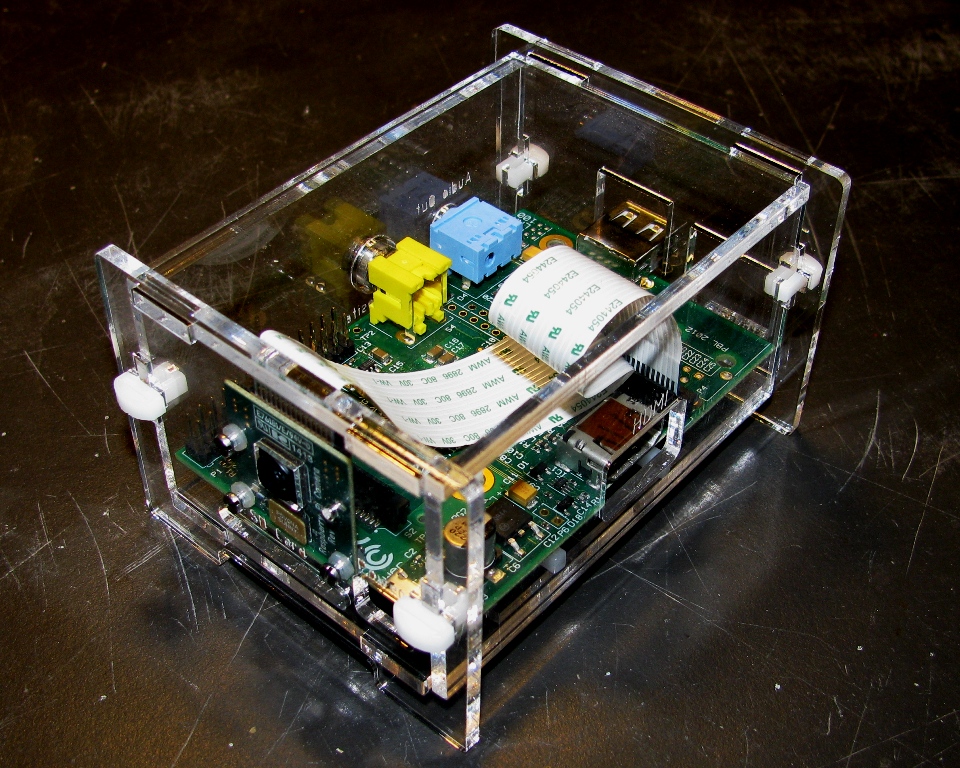
Congratulations! You have successfully assembled your Raspberry Pi Camera Enclosure.