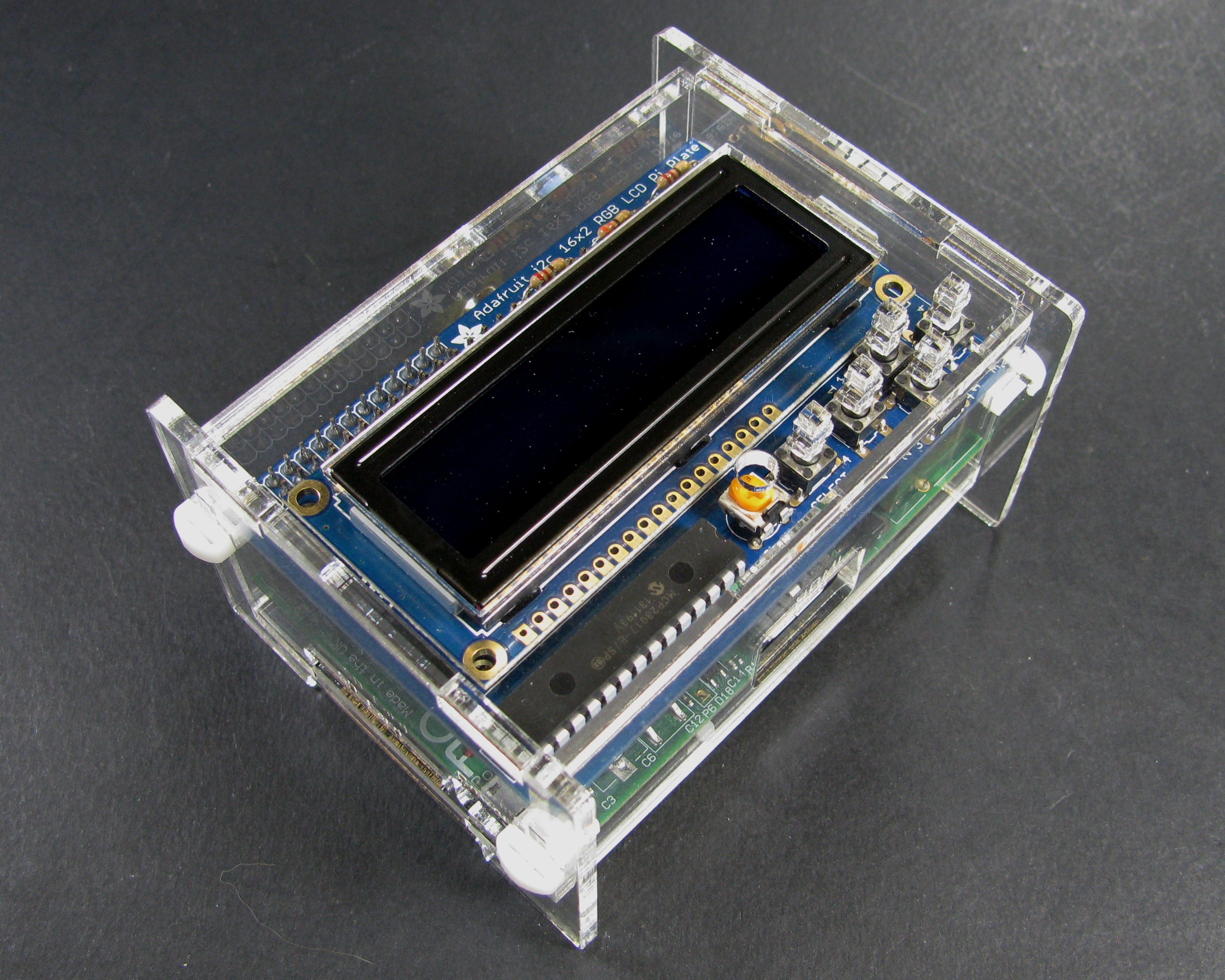
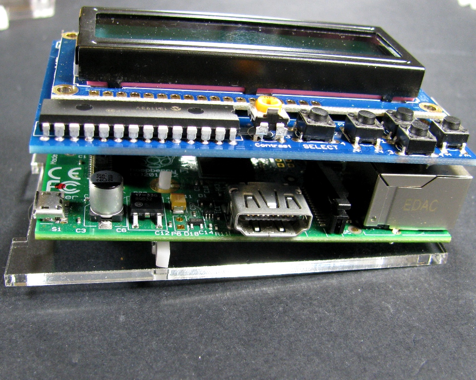
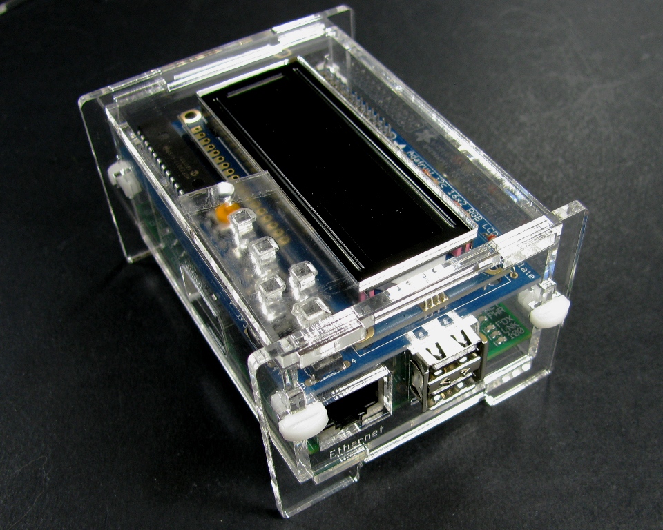
Raspberry Pi and Adafruit LCD + Keypad Pi Plate Enclosure
 Grab the design files here:
Grab a kit here:
Grab the Adafruit LCD + keypad kit here:
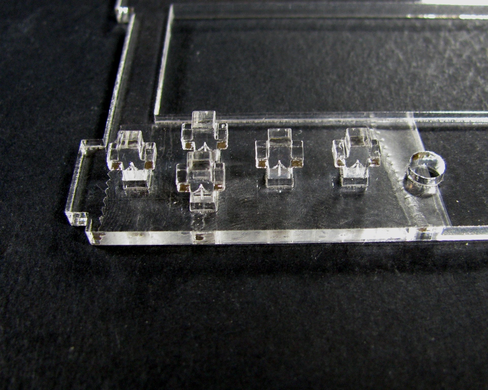
These are the parts for this case
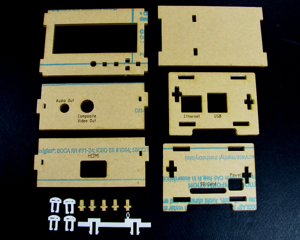
Step 1: Remove the masking
Peel the masking material from both sides of the parts.
Step 2: Begin assembly
Take the Audio/Composite Video out side and attach it to the SD/Power side as shown below. Because of the spacing of the expansion headers it is really important that you do this before assembling the rest of the case!

Step 3: Mount PCB
Take the Bottom plate and set it in front of you as shown:
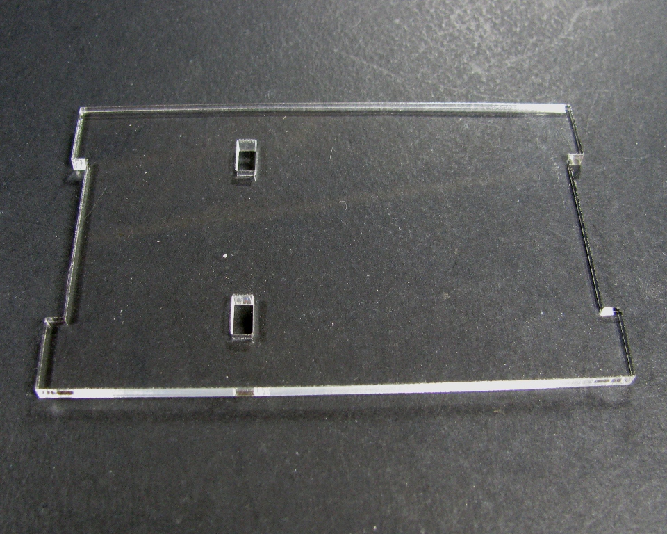
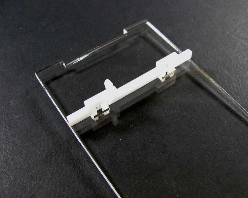
Snap the PCB mounting clip into the slots as shown:
Note that a few very early model B boards did not have mounting holes on the boards. If you have one of these early boards, you'll need to clip off the loop (it's fairly easy to do with a pair of flush cutters) before continuing.
Now snap the PCB onto the PCB mounting clip:
Step 4: Put the two assemblies together
Take the bottom plate with the PCB on it and add it to the two sides already put together as shown below:

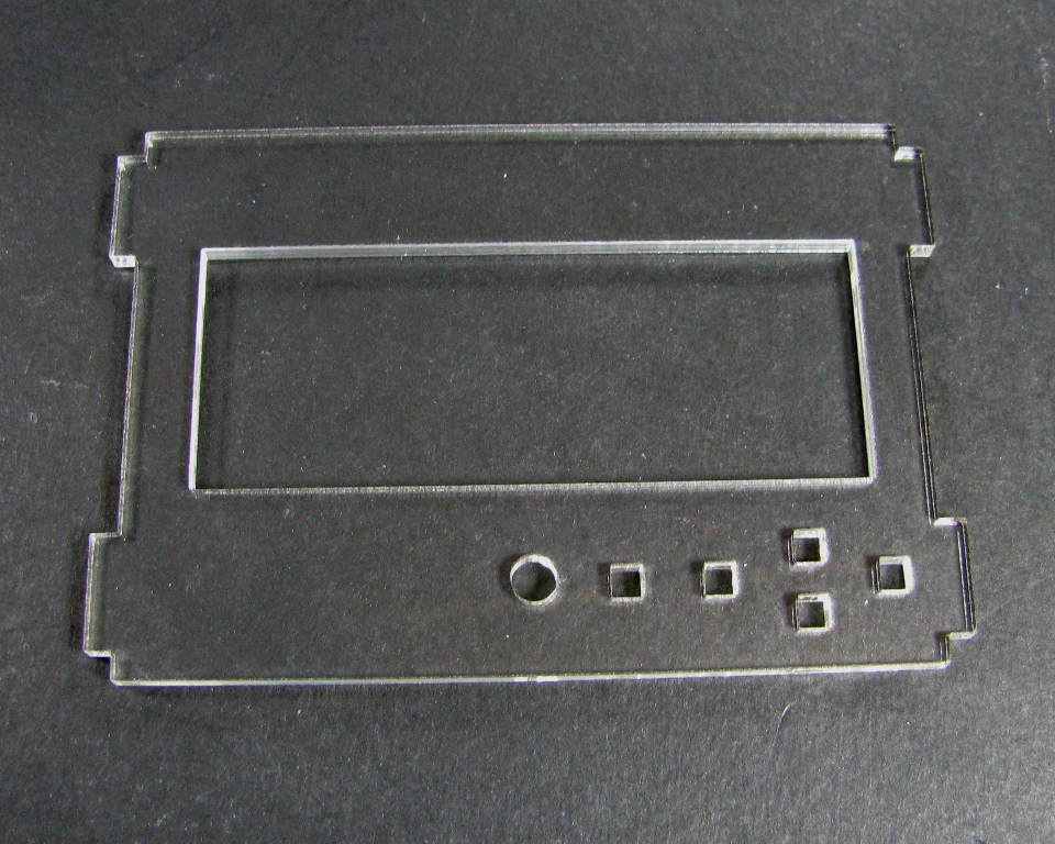
Step 5: Prepare the Top plate
Take the top plate and place it in front of you as shown:
Take a piece of tape and place it over the button holes as shown:
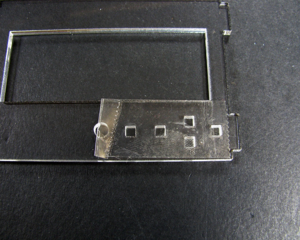
Now flip it over horizontally:
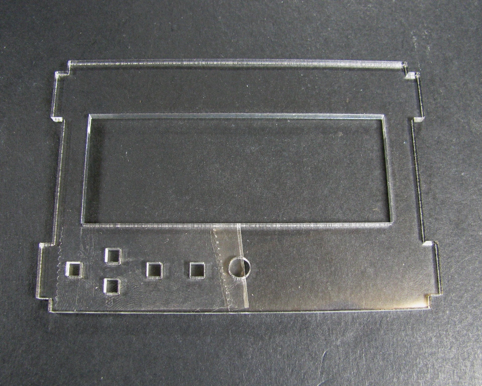
Look at the buttons and notice the arrow in the middle:
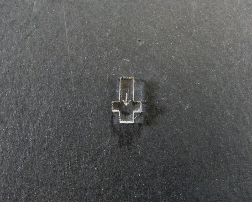
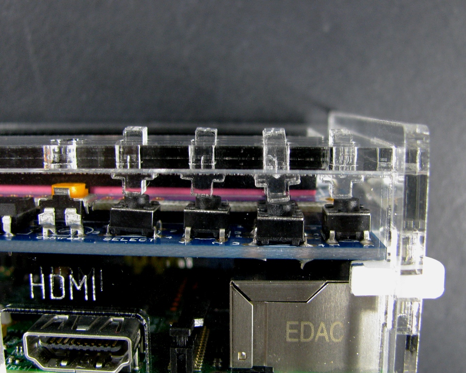
Place the buttons in the holes with the arrows pointing up. Be sure that they are stuck to the tape:
Step 6: Add the Top Plate
Carefully work the tabs into the SD/Power side and around the LCD screen:
Step 7: Attach HDMI side
Take the HDMI side and attach it with a case clip:
Step 8: Attach Ethernet/USB side
Hold onto the case by using the HDMI and Audio sides to sandwich the top and bottom plates and work the tabs into the slots on the Ethernet/USB side. Put clips in place:
Step 9: Remove tape
Peel the tape off of the buttons
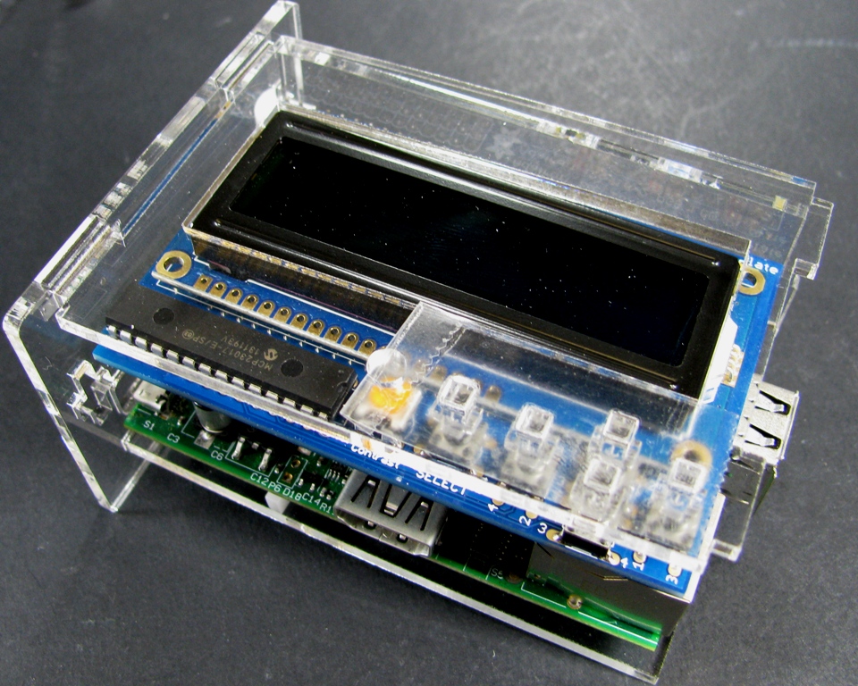
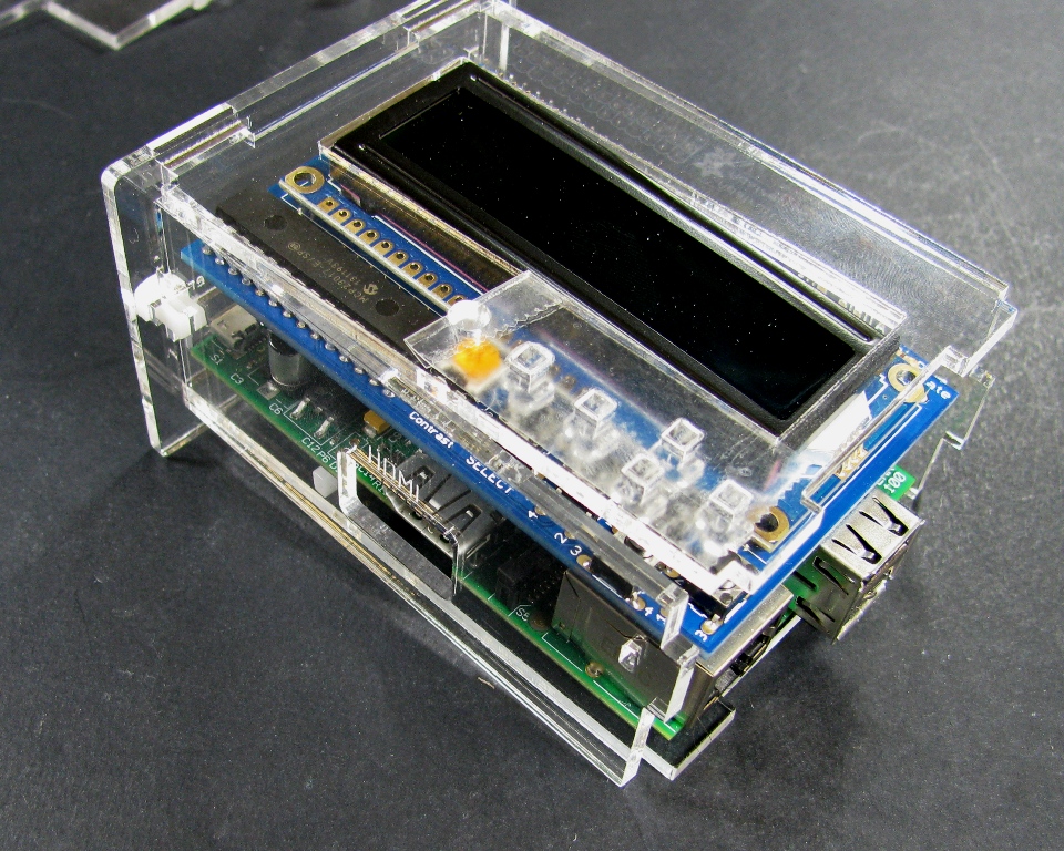
Step 10: ENJOY!
Enjoy using your Raspberry PI with the Adafruit LCD + keypad kit!

