(New) Clear Raspberry Pi Enclosure Assembly

*Note: The version of the Raspberry Pi used in these instructions is Model A,
which lacks an ethernet port and has only one USB port. The assembly process
is the same for both Model A and Model B and the piece for both types is
included in the kit as of 5/20/13. If you picked up one of the older kits and would like an upgrade, email me (craig@built-to-spec.com) and I'll get one out to you.
Step 1: Prep the Parts
The laser cut acrylic parts of the kit have a protective mask that keeps the parts from getting scratched up or marred during cutting. You'll need to peel this mask off all the parts before assembly.
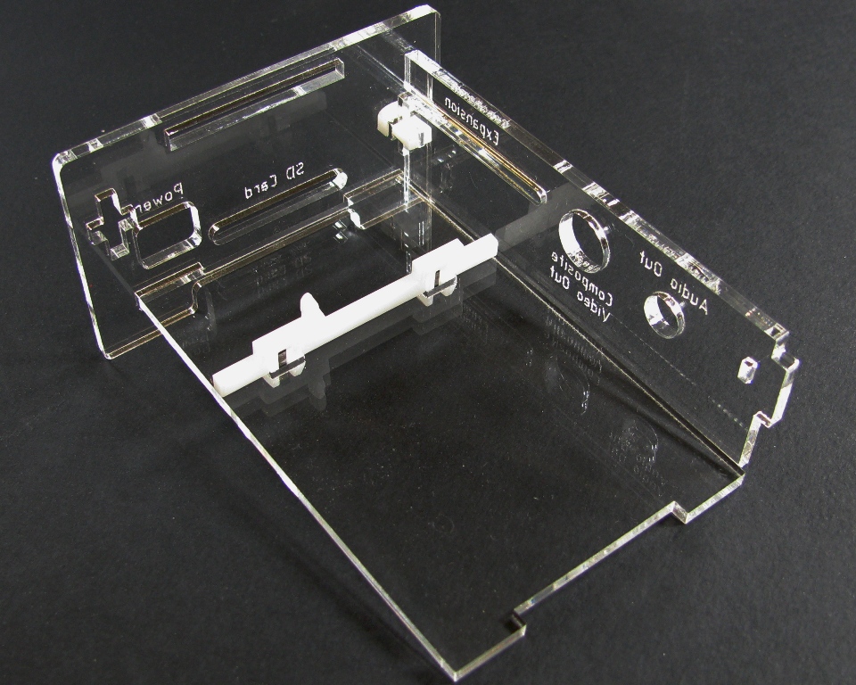
Step 2: Attach SD Card/Power Side and Composite Out/Audio Out Side Together


Take the Composite Out/Audio Out Side and insert the tab into the slot on the right side of the SD Card/Power Side. Snap one of the white clips into place to hold the sides together.
Step 3: Install Bottom
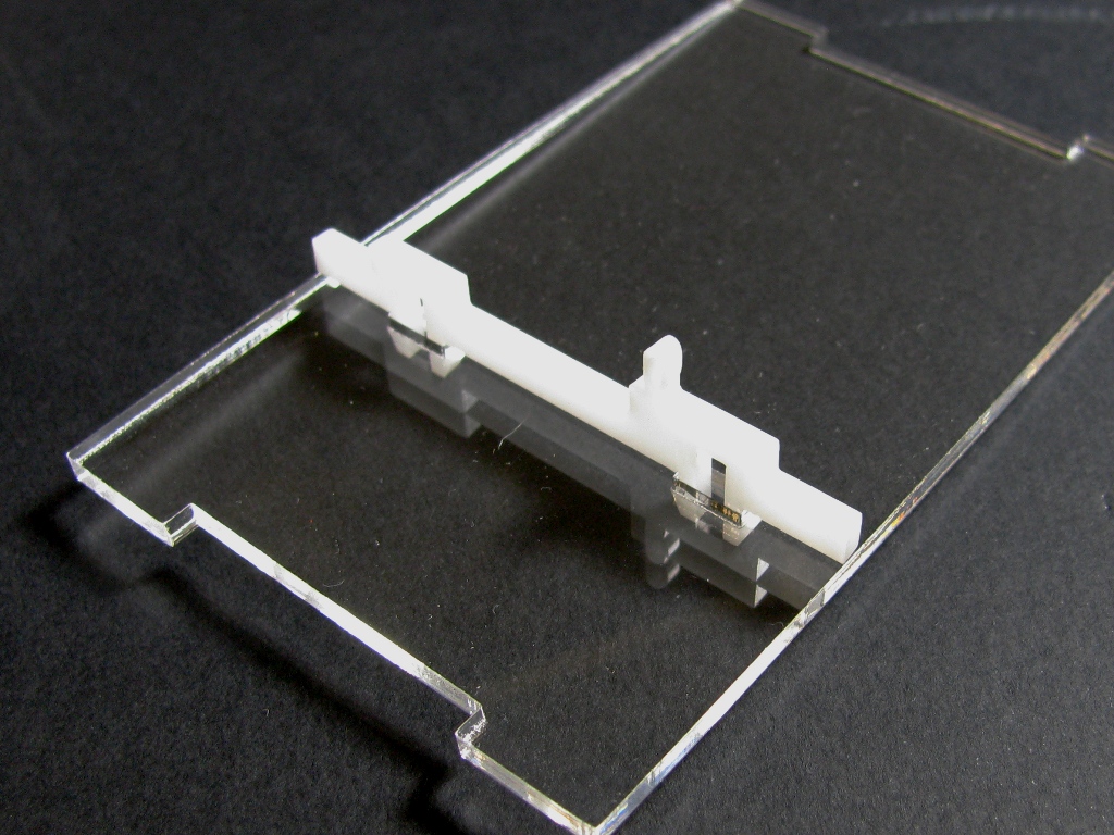
Snap the PCB standoff into the slots on the bottom. Then insert the bottom plate into the SD Card/Power side with the PCB standoff on that side.
Note that a few very early model B boards did not have mounting holes on the boards. If you have one of these early boards, you'll need to clip off the loop (it's fairly easy to do with a pair of flush cutters) before continuing.
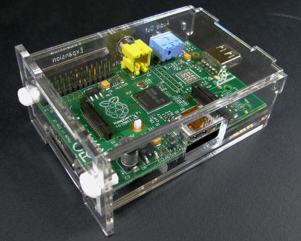
Step 4: Install the Raspberry Pi
Now insert the Raspberry Pi main board, without the SD card in place, and snap it onto the PCB standoff. Be careful to not knock the bottom out.
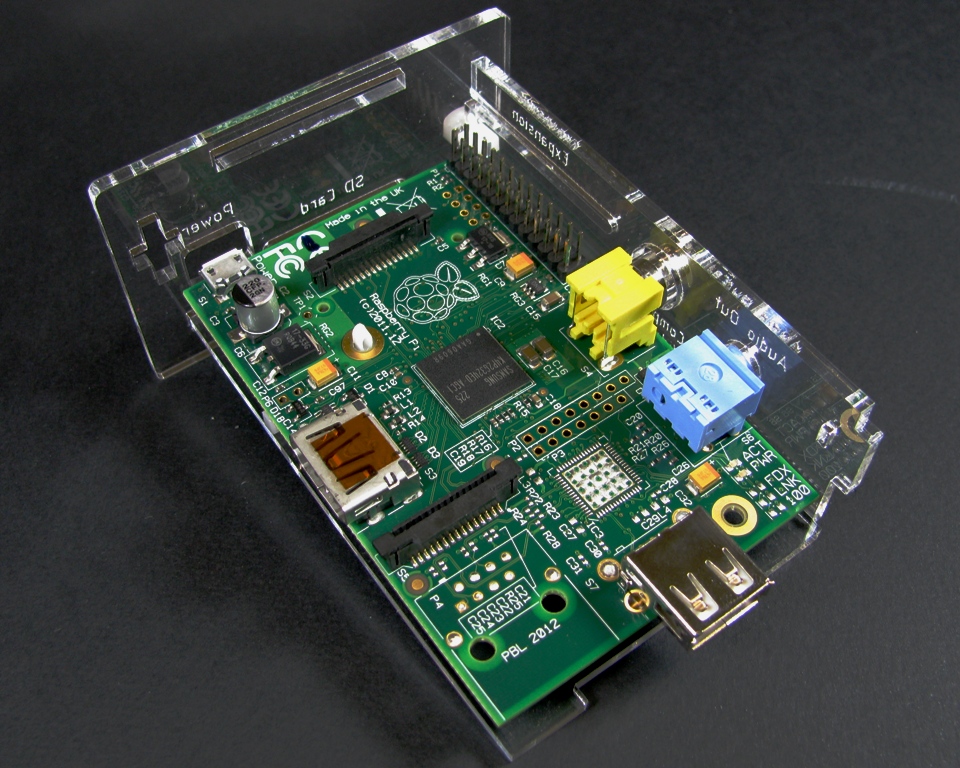
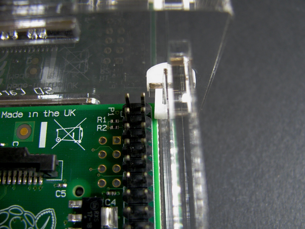
Be sure that the expansion pins are next to the clip as shown in the image below. If not, the board will not fit properly.
Step 5: Install HDMI Side

Slide the HDMI side into place and snap the clip into the slot. It is best if you squeeze the HDMI and Composite Out/Audio Out sides together in one hand to help prevent the bottom and PCB board from falling out.
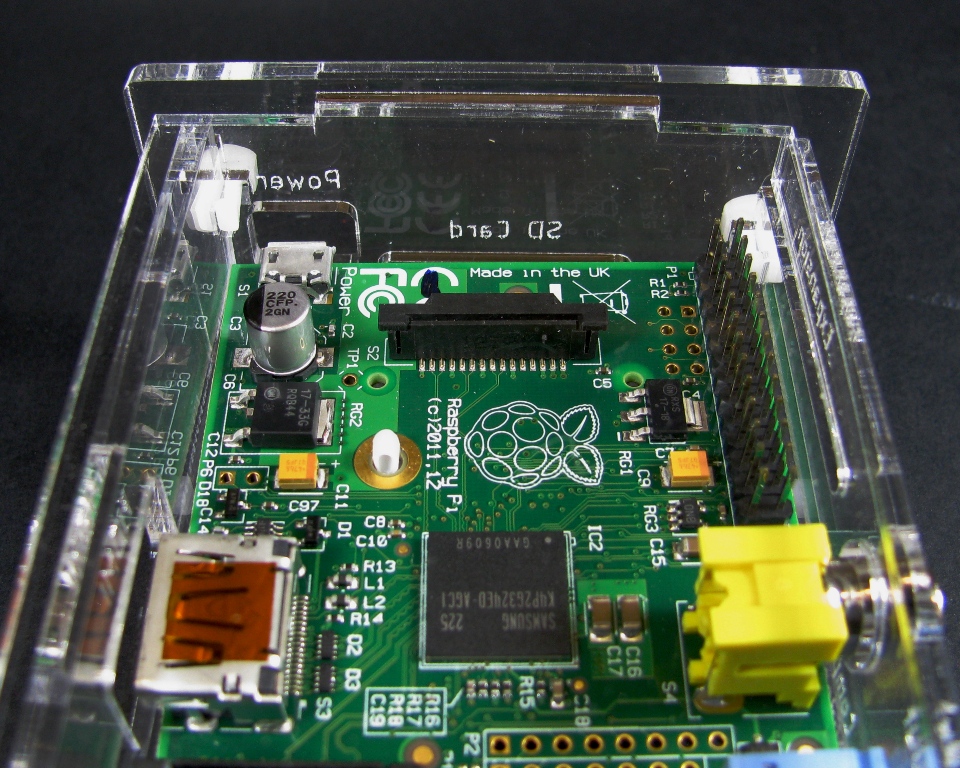
Step 6: Install Top
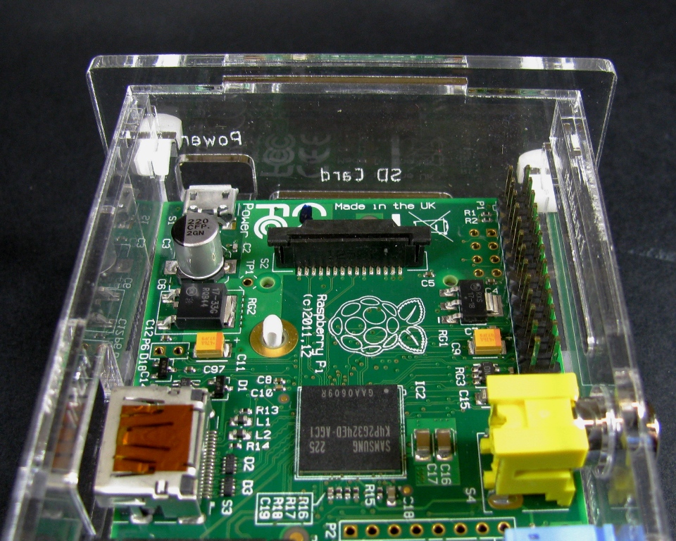
Set the top on the case and slide the wide tab into the SD Card/Power side. The tab on the top plate is slightly offset from center to allow hole alignment with the Adafruit Pi Plate expansion board, so be sure that the edges of the top line up properly with the HDMI and Composite Out/Audio Out sides.
Not correct
Correct
Step 7: Install USB/Ethernet Side
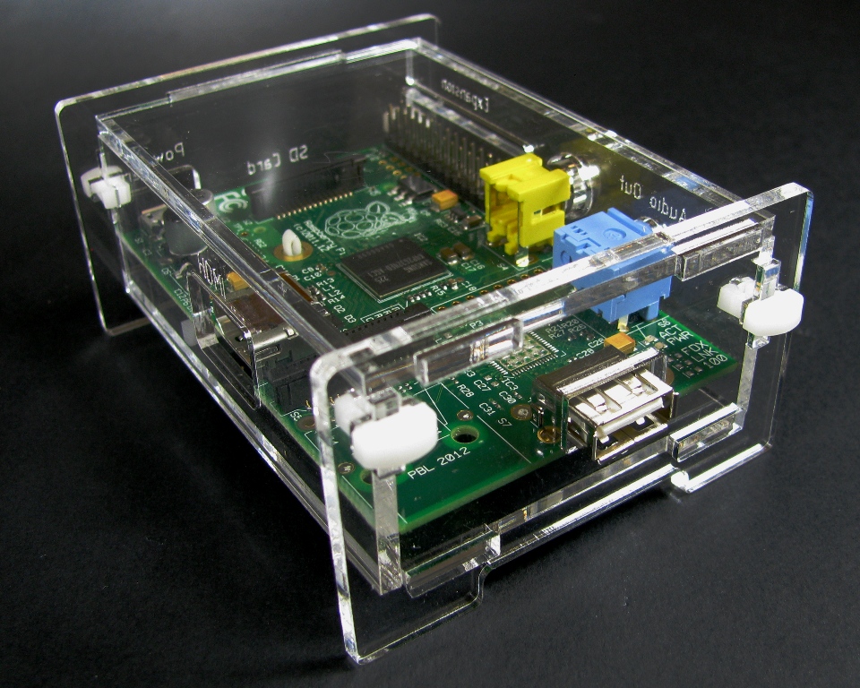
Now, carefully pick up the case and take the USB/Ethernet Side and maneuver it into place. There's a plate for the model A and B versions in each kit, just use the correct one for your board then insert the clips into the slots. Congratulations! You now have a fully assembled Raspberry Pi case!
If you have the Adafruit Pi Plate expansion board and want to keep your Raspberry Pi in a case to use it, you can!


All you need to do with this case is remove the top panel by removing the USB/Ethernet side and then reattach it without the top on. Then you just install the Adafruit Pi Plate board right on top of the Raspberry Pi like normal. The slots in the side panels that were for the top line up perfectly with the screw-terminals on the Adafruit Pi Plate board to allow easy access.


Want one of these cases for yourself? Grab one here:
Want the design files? Grab them from my Thingiverse page:

