Neuron Build Instructions
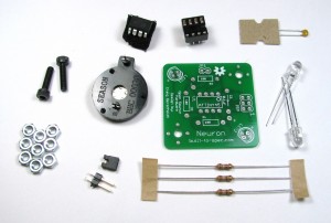
Your Neuron kit should include everything pictured above:
- Three 180 Ohm Resistors
- A Jumper
- A 2-Pin Header
- A 0.1uF Capacitor
- A Programmed ATTiny45 Chip
- An 8-Pin Socket
- A CR2032 Battery Holder
- Two Red (630nm) LEDs
- Two 12mm long M3 bolts
- Eight M3 Nuts (or more, I like to throw in a spare part or two)
Step 0:
I'm not going to go into an introduction on how to solder here, as plenty of other people have already put out great information on learning to solder. Here's a list of resources for learning the basic (and not so basic) soldering skills:
Step 1: Install the Resistors

 When assembling through hole projects like this one, you'll generally want to start with the lowest profile parts first and work your way to the higher ones. Here profile means how far the part sticks off the board. The reason for this general rule is if you assemble from lowest to highest part you can avoid a lot of fumbling with the board because parts will stay in place when you flip the board over if you're soldering on a flat surface.
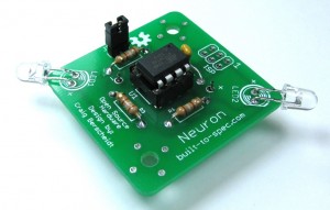
You'll want to solder in the resistors first. Polarity doesn't matter on these parts, so don't worry about which pin of the resistor goes where, so long as the part itself occupies the correct spot on the board (see above pic). The value of the resistors doesn't matter in this case either since all the resistors in the kit are the same value, 180 Ohms. You can easily solder all 3 of the resistors in place at once, or do them one at a time. Insert the leads of the resistor in the correct spot and bend the leads a bit outward like in the above picture to hold the resistors in place when you flip the board over to apply solder. Once you've soldered the resistor leads, clip off the excess.
Step 2: Install the IC Socket
Next we'll install the socket for the IC. Orientation isn't super important for this part, but there should be a notch in the socket toward the side that pin 1 on the IC is on. This notch should be away from the "U1" label on the PCB. Again, you may want to bend a couple of the pins outward to hold the socket in place when you flip the board over to solder it. I tend to bend pins at opposite corners of the socket like shown here.
Step 3: Install the Capacitor

 Next we install the capacitor as shown. Orientation isn't important with this particular type of capacitor, so don't worry about getting the right side in the right hole. Bend the leads out a bit to hold the part in place and clip the excess lead length after soldering like you did with the resistors.
Step 4: Install the LEDs

 Now the time has come to install the LEDs! These parts are polar and it matters what orientation you solder them in place in. The longer lead is the positive lead, so make sure it goes in the hole marked + on the PCB. The LED package also has a small flat section on it that marks the negative side and this flat is also shown on the PCB symbol for the LED and both of these should match up. You'll want to bend the LED leads over so that the LEDs hang off the edge of the PCB as shown. Bend the leads out a bit as before to hold the LEDs in place when you flip the board and cut off the excess lead length after soldering.
Step 5: Install the Header

 Now we need to add the jumper pins. Jumpers and headers can be a little more difficult to solder because they don't typically stay in place when you flip the board over. Use a flat surface, helping hands, or some other holding mechanism to hold the jumper pins in place when soldering. The longer ends should be on the same side as all the other components you've soldered thus far.
Step 6: Place the IC and Install the Jumper

 Next we need to insert the IC into the socket. The IC has a small divot that marks pin 1 on the chip. Make sure this divot is toward the capacitor on the board as shown. Don't apply excessive force to the chip and make sure each pin lines up to a contact in the socket. Now would be a good time to install the jumper on the jumper header as shown as well.
Step 7: Test the Board
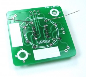
Now the time has come to test your work. It's a good idea to verify that the board is working before you solder down the battery holder since it will cover up many of the solder joints you just made, making it hard to track down and fix problems. Test your board by installing a battery into the battery holder and inserting it in its place on the back of the PCB. Pay attention to the orientation of the battery holder, making sure the side with the tab matches up with the graphic on the PCB. If you've got the jumper in place and everything works, the both LEDs should start blinking (you may have to wiggle the battery holder to get good contact).
Step 8: Install the Battery Holder
Now that you've verified that the board works, take the battery out of the battery holder and solder the battery holder to the board. Again, make sure the tab on the battery holder matches the graphic on the PCB!
Step 9: Install the Standoffs
Now that the soldering part is done, we need to add some hardware that will allow the whole thing to sit level on a flat surface. Start off by threading 3 nuts onto each included M3 bolt. Next, use the remaining nuts to attach the bolts to the Neuron using the two mounting holes on the board as shown. The board should rest flat on a flat surface, allowing you to point it at other Neurons easily.
Modes of Operation
When the jumper pins are shorted, the Neuron will be in "blinky" mode and the LEDs will simply flash in an alternating pattern. When the jumper pins are open (the jumper removed), the Neuron will be in normal or "neuron" mode. In this mode, any pulse of light seen on one LED will be repeated after a short delay on the LED opposite it. Other Neurons can be used to trigger the flash, as well as pulses from other bright light sources and LEDs, but only if the light wavelength is at or above the wavelength of the light being output by the LED (630nm for the standard kit). Touching the leads of the LEDs often triggers the Neuron as well!
In Neuron mode you can chain multiple Neurons together, each one triggering off the last, and even trigger multiple Neurons from a single light pulse to make branching patterns. You can also use a Neuron in blinky mode to trigger a chain of Neurons.
Sticking Neurons to Magnetic Surfaces
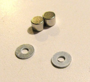
With the help of a couple magnets, Neurons can stick to magnetic surfaces and can be easily stuck in place and repositioned. Magnet kits come with a set of 1/4" neodymium magnets and washers. The washers allow for better contact of the magnets to the nuts. The magnets are stuck on the side opposite the head of the bolts, which actually contact the magnetic object you're sticking the Neurons to, so when you pick one up you don't leave hard to remove magnets behind!
Sound Generation
When in neuron mode, if you attach a piezo speaker to the jumper connector your Neuron will emit a random tone when it is activated. A piezo element is required, normal wire speaker elements will not work! Piezo kits include a jumper connector, an enclosed piezo element, and heat shrink tubing to help reinforce and protect the peizo's soldered connections to the jumper connector. It's best to use some helping hands or some other clamping mechanism to hold the jumper connector when soldering the leads of the piezo to it.
Turning off the Neuron
You may have noticed there's no off switch on the Neuron. To turn off your Neuron, simply slide some thick paper or card stock between the contact and the battery on the battery holder. The paper slip one of your electrical components came on or a small piece of the packaging for the battery can easily be used to do this.


